A permanent magnetic bias magnetic suspension bearing

A magnetic levitation bearing and permanent magnetic bias technology, which is applied to components of pumping devices for elastic fluids, non-variable pumps, pump components, etc., can solve the problem of reducing rotor dynamics safety margins and limiting electronic power devices Select and increase the linear speed of the rotor surface, etc., to achieve the effect of compact structure, increased application range, and high space utilization

Active Publication Date: 2021-09-03
BEIHANG UNIV
View PDF5 Cites 0 Cited by
  • Summary
  • Abstract
  • Description
  • Claims
  • Application Information

AI Technical Summary

Problems solved by technology

[0003] 1. Increase the axial stator coil current. This method will increase the copper consumption of the coil, increase the coil temperature, and increase the loss. At the same time, the large current will limit the selection of electronic power devices
[0004] 2. Increase the radius of the thrust disc. This method will increase the wind friction loss of the rotor, increase the linear speed of the rotor surface, reduce the safety margin of the rotor dynamics, and reduce the stability of the system control.
[0006] It can be seen that under the existing technical means, to improve the axial bearing capacity, it will affect other performance indicators such as loss and volume.

Method used


Image

  • A permanent magnetic bias magnetic suspension bearing
  • A permanent magnetic bias magnetic suspension bearing
  • A permanent magnetic bias magnetic suspension bearing

Examples


Embodiment Construction

[0024] The present invention will be further described in detail below in conjunction with the accompanying drawings and specific embodiments.

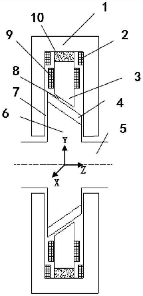
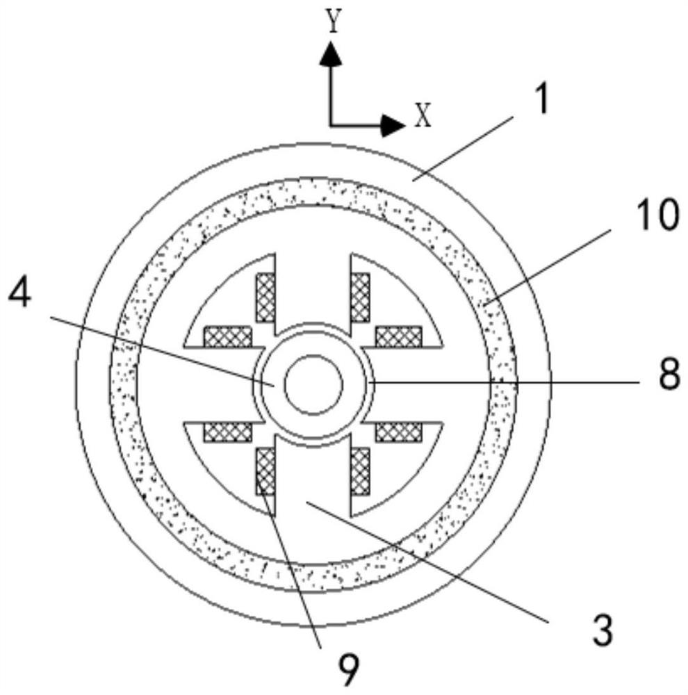
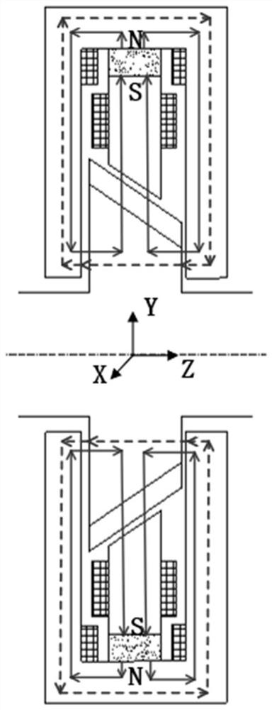
[0025] like figure 1 , figure 2 As shown, the basic form of the present invention is: axial magnetic guide ring 1, axial coil 2, radial coil 9, conical rotor lamination 4, conical thrust disc 6, rotor shaft 5, a conical radial stator iron Core 3, a ring 10 of permanent magnets. The axial magnetic guide ring 1 and the inner tapered radial stator core 3 are connected through the permanent magnet ring 10, which is radially magnetized and provides axial and radial bias magnetic fields at the same time; the conical thrust The front and back of the disk 6 are planes, forming an axial magnetic gap with the axial magnetic guide ring 1; two sets of axial coils are respectively located on the upper and lower sides of the axial magnetic guide ring 1 to provide an axial control magnetic field; the tapered radial stator core 3 It is made of a ...


PUM


Abstract

The invention discloses a permanent magnetic bias magnetic suspension bearing, which comprises an axial magnetic suspension bearing and a radial magnetic suspension bearing placed inside the axial magnetic suspension bearing. The permanent magnet connects the axial magnetic guide ring and the radial stator core, and provides axial The radial bias magnetic field; the front and back of the conical thrust disc are planes, forming an axial magnetic gap with the axial magnetic ring; the axial coil is located on the upper and lower sides of the axial magnetic ring to provide an axial control magnetic field; the radial stator The center of the iron core forms a tapered hole, and the outside of the conical thrust disc is a tapered rotor stack; the outer peripheral edge of the tapered rotor stack is tapered, and the tapered surface of the edge is parallel to the surface of the tapered hole of the radial stator core. Form a tapered radial magnetic gap; the radial magnetic flux generates a force perpendicular to the radial conical surface at each radial magnetic pole, so the radial magnetic bearing can provide an axial unloading force while outputting the radial force, A small axial current and a small axial thrust disc can provide a large axial load.

Description

technical field [0001] The invention relates to the technical field of non-contact magnetic bearings, in particular to a small-volume, low-power permanent magnetic bias three-degree-of-freedom magnetic suspension bearing, which can be used as non-contact support for rotating parts in mechanical equipment such as compressors, blowers, and molecular pumps. Background technique [0002] Magnetic suspension bearings have the advantages of no friction, no wear, high speed, easy control and long life. Since there is no mechanical contact between the stator and the rotor, the rotor of the magnetic bearing can reach a very high speed, so in high-speed rotating machinery, the magnetic bearing has unique advantages. When magnetic bearings are used in blowers, compressors, etc., the pressure difference between the inlet and outlet of the impeller produces a very large axial load on the rotor, so higher requirements are put forward for the design of axial magnetic bearings. In order to...

Claims


Application Information

Patent Timeline
Patent Type & Authority Patents(China)
IPC IPC(8): F04D29/058
CPCF04D29/058
Inventor 郑世强王棣乐韵王坤
Owner BEIHANG UNIV
Why Eureka
Try Eureka