Spiral friction damping device for electrical equipment

A technology for electrical equipment and shock absorbing devices, applied in the direction of friction shock absorbers, shock absorbers, mechanical equipment, etc., can solve the problems of low frictional energy consumption, residual deformation, frequent replacement, etc., and achieve a clear shock absorbing mechanism and improved Friction performance, the effect of ensuring safe operation

Pending Publication Date: 2020-05-05
CHINA ELECTRIC POWER RES INST +1
View PDF3 Cites 1 Cited by
  • Summary
  • Abstract
  • Description
  • Claims
  • Application Information

AI Technical Summary

Problems solved by technology

The key equipment such as lightning arresters and transformers in substation (converter) stations are pillar electrical equipment. In order to ensure insulation performance, such equipment usually uses porcelain materials. However, the electrical clearance requires the equipment to have a thin and high structure. It is difficult to take into account the anti-seismic performance in manufacturing, resulting in serious earthquake damage to pillar equipment
[0003] In order to improve the anti-seismic performance of the pillar electrical equipment in the station in the high-seismic intensity area, the patent ZL 201010524100.6 is a shock-absorbing device based on the deformation and energy dissipation of lead alloy, which provides a trigger action when an earthquake occurs, and the hysteresis of the shock absorber under the reciprocating load. The back curve is a quadrilateral occupying four quadrants, but since the shock absorbing device cannot automatically reset, there is residual deformation after the earthquake, and the equipment may accumulate adverse effects such as tilt and offset
Chinese patents CN 104482108 B and CN 105604203 B provide friction-type shock absorbers that can be reset after an earthquake. However, most of these shock absorbers have a single friction contact surface, simple friction tracks, low frictional energy consumption, and poor wear resistance of materials. Frequent replacement, short service life, far from meeting the requirements for safe and stable operation of the power station, and affecting shock absorption performance

Method used


Image

  • Spiral friction damping device for electrical equipment
  • Spiral friction damping device for electrical equipment
  • Spiral friction damping device for electrical equipment

Examples


Embodiment 1

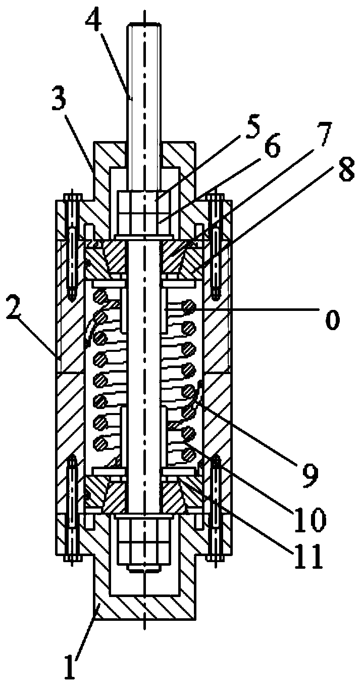
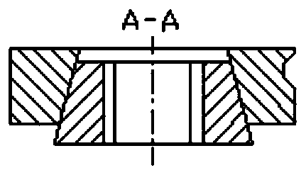
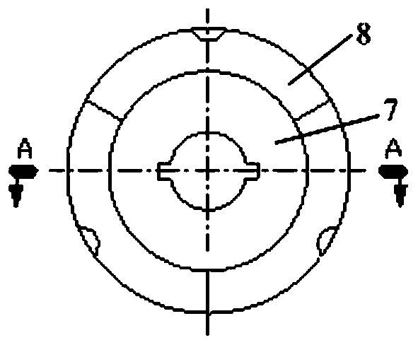
[0046] like figure 2 As shown, the inner ring 7 of the friction assembly is a single-taper ring, and the outer ring 8 is a single-taper ring composed of three segmented rings of the same size. The tapered surfaces of the inner ring 7 and the outer ring 8 fit together, There is a guide groove on the outer side of the outer ring 8, and a corresponding spiral guide ridge 9 is provided on the inner wall of the cylinder body 2. The two form a spiral motion pair. When the transmission shaft 4 moves up and down, the outer ring 8 is driven to move up and down, and the outer ring 8 is rotated at the same time. .

[0047] The friction components include the following components by mass percentage: C0.4%, Al 1.2%, Si 0.45%, Mo1.5%, V 0.15%, Ti 0.05%, B 0.005%, Re 0.2%, Mg 0.5%, The balance is Fe and impurities; the barrel includes the following components by mass percentage: C0.3%, Si 0.8%, W 0.9%, Cr3.9%, Ti1.2%, Mn4%, Mo0.9%, S0.04%, the balance is iron and impurities; the guide rid...

Embodiment 2

[0049] like image 3 As shown, the friction assembly is composed of two single-tapered inner rings 7 and a double-tapered outer ring 8. The outer ring 8 is a single-tapered ring composed of three segmented rings of the same size. The tapered surfaces of the ring 7 and the outer ring 8 fit together, the outer ring 8 is provided with a guide groove, and the inner wall of the cylinder 2 is provided with a corresponding spiral guide ridge 9, the two form a spiral motion pair, and when the transmission shaft 4 moves up and down, it drives The outer ring 8 moves up and down, and the outer ring 8 is rotated at the same time.

[0050] The friction components include the following components by mass percentage: C0.48%, Al 1.0%, Si 0.80%, Mo1.2%, V 0.15%, Ti 0.05%, B 0.005%, Re 0.22%, Mg 0.3%, The balance is Fe and impurities; the barrel includes the following components by mass percentage: C0.5%, Si 0.6%, W 1.2%, Cr2.9%, Ti1.8%, Mn2%, Mo1.2%, S0.02%, the balance is iron and impuritie...

Embodiment 3

[0052] like Figure 4 As shown, guide ridges are provided on the outside of the outer ring 8, and guide grooves are provided on the inside of the corresponding cylinder 2, and the two form a helical motion pair.


PUM


Abstract

The invention provides a spiral friction damping device for electrical equipment. The electrical equipment is pillar type electrical equipment. The damping device is positioned between the electricalequipment and an equipment support, wherein the device comprises a vertically-arranged barrel, a transmission shaft axially arranged in the barrel and a damping assembly arranged around the transmission shaft; the damping assembly comprises an elastic assembly and vertical friction assemblies positioned at the two ends of the elastic assembly; the friction assemblies comprise the upper friction assembly and the lower friction assembly which are symmetrically arranged; and the upper friction assembly and the lower friction assembly are composed of an inner ring and an outer ring which are attached through conical surfaces correspondingly. According to the spiral friction damping device, the damping performance of the damping device is effectively improved, and the service life of the damping device is greatly prolonged.

Description

technical field [0001] The invention relates to a shock absorbing device, in particular to a spiral friction shock absorbing device used for pillar electrical equipment in a substation. Background technique [0002] The distribution of energy bases and power loads is uneven, and a large number of substations (conversion) stations are built in areas with high seismic intensity and unfavorable earthquake resistance. The key equipment such as lightning arresters and transformers in substation (converter) stations are pillar electrical equipment. In order to ensure insulation performance, such equipment usually uses porcelain materials. However, the electrical clearance requires the equipment to have a thin and high structure. It is difficult to take into account the anti-seismic performance in manufacturing, resulting in serious earthquake damage to pillar equipment. [0003] In order to improve the anti-seismic performance of the pillar electrical equipment in the station in ...

Claims


Application Information

Patent Timeline
Patent Type & Authority Applications(China)
IPC IPC(8): F16F13/00F16F7/04
CPCF16F7/04F16F13/005
Inventor 程永锋林森卢智成朱祝兵李圣刘振林王海菠孙宇晗孟宪政张谦韩嵘高坡薛耀东
Owner CHINA ELECTRIC POWER RES INST
Why Eureka
Try Eureka