Cleaning machine

A washing machine and washing cavity technology, applied in the field of washing machines, can solve the problems of large installation space, limited sink washing space, high cost, etc., and achieve the effects of preventing deformation due to heat or cold, improving super-cleaning effect, and reducing production costs.

Pending Publication Date: 2020-05-08
NINGBO FOTILE KITCHEN WARE CO LTD
View PDF2 Cites 2 Cited by
  • Summary
  • Abstract
  • Description
  • Claims
  • Application Information

AI Technical Summary

Problems solved by technology

Among them, for the welding process, due to the large amount of welding deformation of the stainless steel material, it is difficult to control the dimensional accuracy of the sink, which limits the overall shape of the sink body, resulting in a single structure of the sink body, which in turn restricts the sink type washing machine. The development of more functional structures, and the welding process has extremely high requirements on the welding mold, the welding efficiency is low, and the cost is high; for th

Method used


Image

  • Cleaning machine
  • Cleaning machine
  • Cleaning machine

Examples


Embodiment 1

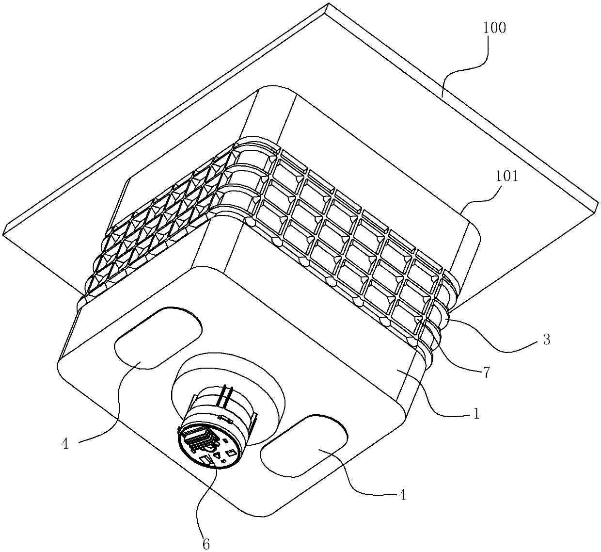
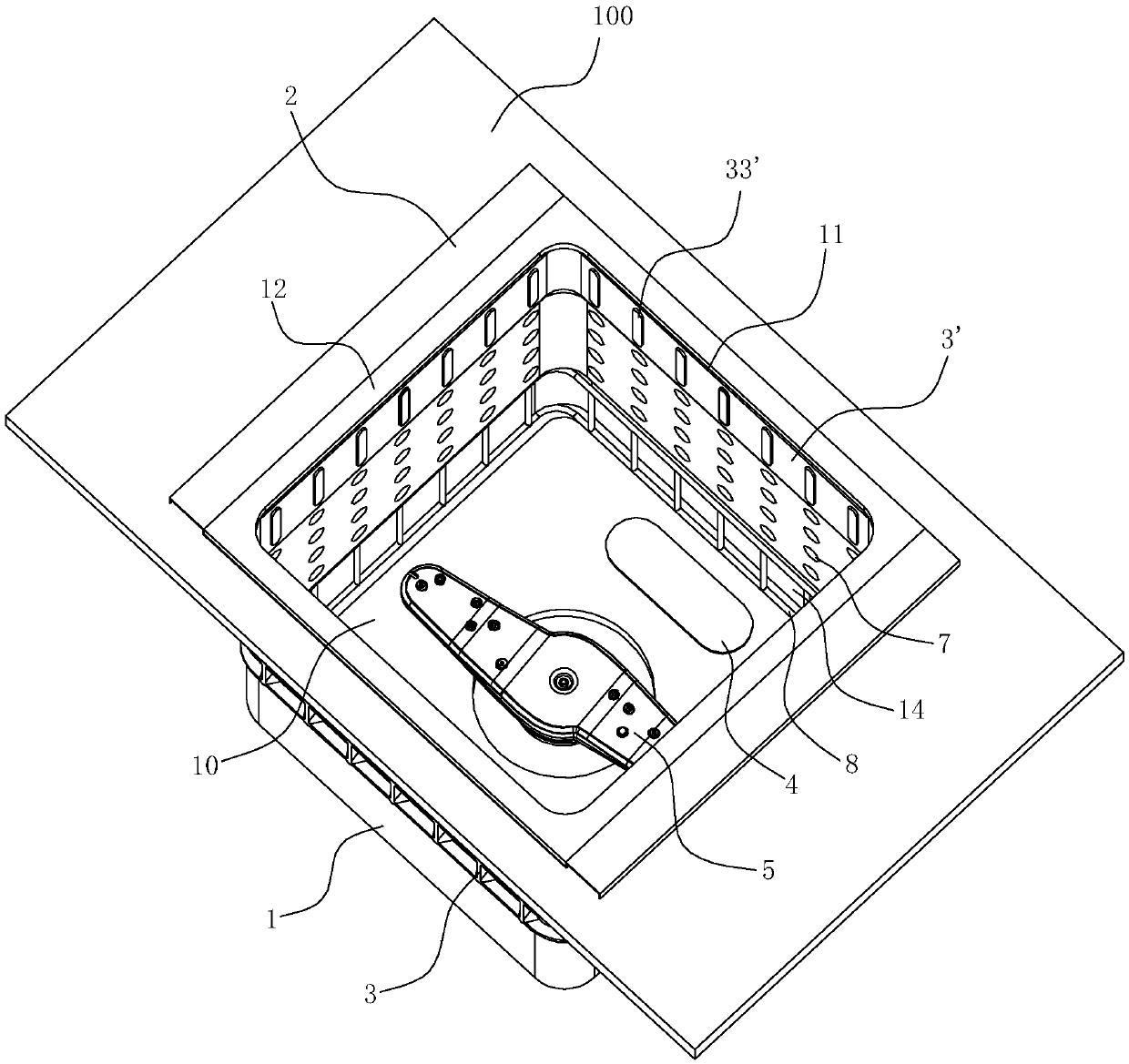
[0044] Such as Figure 1-9 As shown, the cleaning machine of this embodiment is a sink type cleaning machine, including a sink body 1 with a washing cavity 10, the sink body 1 needs to be installed on a cabinet table 100 for use, and the cabinet table 100 is provided with a hole for installing the sink body 1 Port 101 is installed. The top of the sink body 1 has an opening 11 communicating with the washing cavity 10 .

[0045] The bottom of the water tank body 1 in this embodiment is provided with a water pump 6 capable of lifting water from the bottom of the water tank body 1 and spraying upwards through the spray arm 5 . The bottom of the sink body 1 is provided with an ultrasonic generator 4, which structure can effectively improve the cleaning effect.

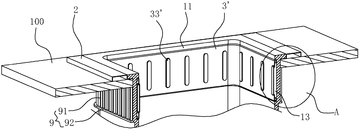
[0046] In this embodiment, the opening 11 of the sink body 1 is made of metal at least where it is in contact with the countertop 100 , and the lower part of the sink body 1 is made of plastic. Considering that the load-...

Embodiment 2

[0055] The difference between this embodiment and Embodiment 1 lies in that the structure of the second metal reinforcement 8' is different.

[0056] Such as Figure 10 As shown, the second metal reinforcement 8' of this embodiment is shaped as an annular plate extending up and down in the second accommodation groove 14, and the upper edge of the annular plate is in contact with the upper edge of the second accommodation groove 14. The lower edge of the plate is in contact with the lower edge of the second receiving groove 14 . The upper edge of the annular plate is bent into the second accommodating groove 14 to form a fourth U-shaped structure 81 ′ with the opening facing downwards. contact, the lower edge of the annular plate is bent into the second accommodating groove 14 to form a fifth U-shaped structure 82 ′ with the opening facing upwards, and the outer side of the fifth U-shaped structure 82 ′ is connected with the second accommodating groove 14 The inner walls are ...


PUM


Abstract

The invention relates to a cleaning machine, which comprises a plastic water tank body with a washing cavity. The cleaning machine further comprises a first metal reinforcer, a second metal reinforcer, a first metal reinforcer and a second metal reinforcer, the first metal reinforcer is arranged on the inner wall face of the upper portion of the water tank body, the second metal reinforcer is arranged on the inner wall face of the lower portion of the water tank body, and at least a first reinforcing rib is arranged in the middle of the peripheral wall of the water tank body. The water tank body is made of plastic, the plasticity is high, the depth of the tank body can be increased conveniently according to needs, and the production cost is greatly reduced; the first metal reinforcer, thesecond metal reinforcer and the first reinforcing rib can prevent the water tank body from being heated or cooled to deform, noise generated when water flow impacts the inner wall of the water tank body can be lowered, the first metal reinforcer can increase the condensation speed of high-temperature steam, the drying speed in the washing cavity is increased, and the cleaning effect is improved.

Description

technical field [0001] The invention relates to a kitchen appliance product, in particular to a washing machine for washing tableware, vegetables or fruits. Background technique [0002] Along with improving day by day of people's living standard, dishwasher more and more enters family as a kind of kitchen appliance product. Dishwashers on the market are generally divided into three types: table type, cabinet type, and tank type. Among them, the table type dishwasher is an integral independent structure, which is generally used on the table; the cabinet type dishwasher is also an independent structure. However, it needs to be embedded in the kitchen cabinet for use; the sink dishwasher is combined with the sink and is generally installed in the kitchen cabinet for use. [0003] At present, the structure of the more mature sink-type cleaning machines on the market is mainly as described in the Chinese patent "Sink-type cleaning machine" (application number: CN201310750968.1)...

Claims


Application Information

Patent Timeline
IPC IPC(8): A47L15/42A47L15/48A47L15/13A47L15/00A47J43/24
CPCA47J43/24A47L15/0086A47L15/13A47L15/42A47L15/483
Inventor 徐慧顾洪良王式兴朱灯光
Owner NINGBO FOTILE KITCHEN WARE CO LTD
Why Eureka
Try Eureka