Intelligent driving vehicle transverse control method and control system

A lateral control and intelligent driving technology, applied in the direction of control devices, etc., can solve the problems of difficulty in mass production, large installation space for lateral control systems, and high cost

Active Publication Date: 2020-05-08
LIANCHUANG AUTOMOBILE ELECTRONICS
View PDF17 Cites 8 Cited by
  • Summary
  • Abstract
  • Description
  • Claims
  • Application Information

AI Technical Summary

Problems solved by technology

However, the lateral control system modified by this method requires a large installation space, which makes the modified vehicle central control not very beautiful, and th

Method used


Image

  • Intelligent driving vehicle transverse control method and control system
  • Intelligent driving vehicle transverse control method and control system
  • Intelligent driving vehicle transverse control method and control system

Examples


no. 1 example

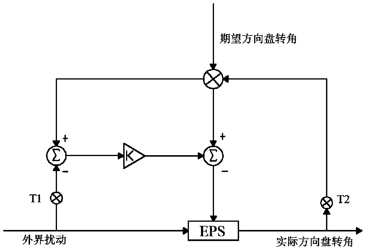
[0074] refer to figure 1 As shown, the first embodiment of a drivable vehicle lateral control method provided by the present invention includes the following steps:

[0075] S1, according to the vehicle power steering characteristics, establish a torque calibration simulation model of the feedforward control system;

[0076] The vehicle power steering characteristic is the relationship among speed, steering wheel angle and steering wheel power torque obtained by calibrating different steering wheel angles under preset speed conditions;

[0077] S2. Establish a torque calibration simulation model of the feedback control system according to the characteristics of the vehicle power steering;

[0078] S3, by setting the expected working conditions, adjust the parameters of the torque calibration simulation model of the feedforward control system and the torque calibration simulation model of the feedback control system according to the parameter adjustment rules;

[0079] S4, ve...

no. 2 example

[0083] A second embodiment of a drivable vehicle lateral control method provided by the present invention includes the following steps:

[0084] S1, according to the vehicle power steering characteristics, establish a torque calibration simulation model of the feedforward control system;

[0085] The vehicle power steering characteristic is the relationship among speed, steering wheel angle and steering wheel power torque obtained by calibrating different steering wheel angles under preset speed conditions;

[0086]

[0087]

[0088] Among them, z 1 ,z 2 ,z 3 are different state observers; l 1 , l 2 , l 3 is the observer gain coefficient; θ is the desired steering wheel angle; J m is the equivalent moment of inertia of the steering system; M r is the steering wheel torque, δ is the set threshold, and ε is the transmission ratio of the steering system.

[0089] S2. Establish a torque calibration simulation model of the feedback control system according to the char...


PUM


Abstract

The invention discloses an intelligent driving vehicle transverse control method. The method comprises the steps of: establishing a transverse control feedforward control system model, a feedback control system model, a feedforward control torque calibration simulation model and a feedback control torque calibration simulation model; performing first parameter adjustment on the feedforward controltorque calibration simulation model and the feedback control torque calibration simulation model; performing real vehicle verification on feedforward control and feedback control torque calibration simulation model parameters obtained by first parameter adjustment; changing different expected working conditions to repeatedly execute the verification steps, calibrating parameters of the feedforward control and feedback control torque calibration simulation model under different expected working conditions, and obtaining optimal parameters of the feedforward control and feedback control torquecalibration simulation model; and performing parameter optimization on the feedforward control torque calibration simulation model and the feedback control torque calibration simulation model by usingthe optimal parameters, and performing simulation debugging on the remaining uncalibrated parameters to obtain all calibration parameters. The invention further discloses an intelligent driving vehicle transverse control system.

Description

technical field [0001] The invention relates to the field of automobiles, in particular to an intelligent driving vehicle lateral control method. The invention also relates to an intelligent driving vehicle lateral control system. Background technique [0002] Intelligent driving technology is a branch of the field of artificial intelligence that is developing very rapidly, and intelligent networking has become the strategic commanding heights of domestic and foreign OEMs. Precise lateral control is the basis for realizing the functional algorithms of intelligent driving vehicles. However, the steering-by-wire technology is not yet mature, and there are obstacles in policy. So far, the only mass-produced steer-by-wire model is the Infiniti Q50, and it has been recalled in large numbers due to steer-by-wire problems within one year of its launch. [0003] At present, there are roughly two types of lateral control modifications for intelligent vehicles: [0004] The first ...

Claims


Application Information

Patent Timeline
IPC IPC(8): B60W30/02B60W10/20B60W50/00
CPCB60W10/20B60W30/025B60W50/00B60W2050/0011B60W2050/0022
Inventor 陈英箭栗工郭嘉
Owner LIANCHUANG AUTOMOBILE ELECTRONICS
Why Eureka
Try Eureka