Feeding and discharging device and detection equipment

A technology for testing equipment and turning materials, applied in lighting and heating equipment, conveyor control devices, transportation and packaging, etc., can solve the problems of large space occupation and high manufacturing cost

Pending Publication Date: 2020-05-08
JOINT STARS TECH
View PDF0 Cites 5 Cited by
  • Summary
  • Abstract
  • Description
  • Claims
  • Application Information

AI Technical Summary

Problems solved by technology

[0004] Therefore, the technical problem to be solved by the present invention is to overcome the defects of high manufacturing cost and large space occu

Method used


Image

  • Feeding and discharging device and detection equipment
  • Feeding and discharging device and detection equipment
  • Feeding and discharging device and detection equipment

Examples


Embodiment

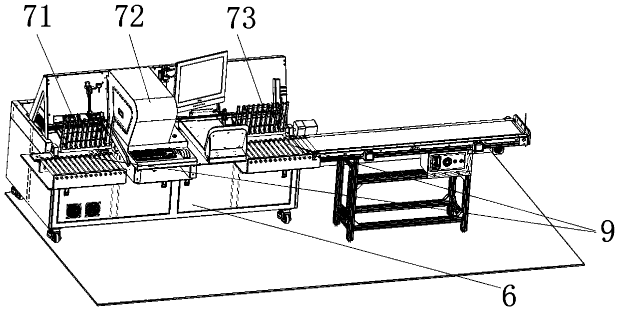
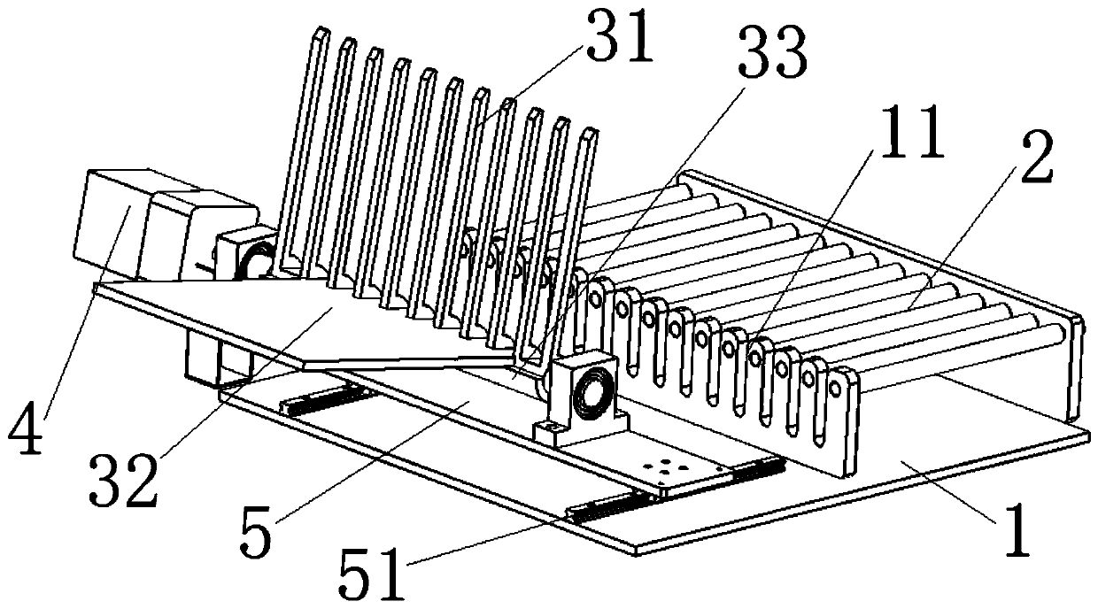
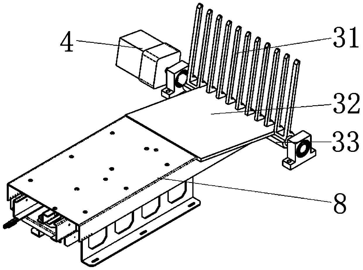
[0049] like figure 1 A detection device shown includes a base frame 6, and fixed on the base frame 6: a loading area 71, a detection area 72, an unloading area 73 and a limit piece 8, and the workpieces to be processed pass through the loading area in sequence 71. Detection area 72 and feeding area 73. Wherein in feeding area 71, and in unloading area 73, be respectively provided with such as Figure 2 to Figure 3 The shown loading and unloading device 9; a detection device is provided in the detection area 72, specifically, the detection device can be a visual detection device; the limit member 8 has an inclined limit surface, and the inclined limit surface is inclined upward along the direction away from the conveying line , the second support member 32 in the loading and unloading device 9 overlaps the inclined limit surface when transferring the workpiece to be processed. Specifically, the workpiece to be processed may be a PCB board or others.

[0050] It should be not...


PUM


Abstract

The invention discloses a feeding and discharging device and detection equipment. The feeding and discharging device comprises a conveying line, a material overturning part, and a material overturningand driving part, wherein the conveying line is used for conveying a to-be-treated workpiece; the material overturning part at least comprises a first supporting part and a second supporting part which are arranged at an angle, the first supporting part is provided with a conveying state which is arranged on the conveying line in a penetrating mode to take the to-be-treated workpiece on the conveying line or place the borne to-be-treated workpiece on the conveying line, and a transfer state which overturns under the driving force to transfer the borne to-be-treated workpece to the second supporting part or the conveying line. The material overturning part is arranged, compared with a mechanical arm and a conveying line for feeding and discharging in the prior art, the manufacturing cost of the material overturning part, the material overturning and driving part and the like is far lower than the manufacturing cost of the mechanical arm, the occupied space of the material overturning part, the material overturning and driving part and the like is far smaller than the occupied space of the mechanical arm, thus the manufacturing cost is lowered, and the occupied space is reduced.

Description

technical field [0001] The invention relates to the technical field of PCB board processing, in particular to a loading and unloading device and detection equipment. Background technique [0002] The PCB board is a printed circuit board, also known as a printed circuit board, a printed circuit board, or a printed board for short. It uses an insulating board as the base material and cuts it to a certain size. At least one conductive pattern is attached to it, and there are holes (such as Component holes, fastening holes, metallized holes, etc.), used to replace the chassis of the previous electronic components and realize the interconnection between electronic components. [0003] At present, in order to distinguish the quality of the PCB board, the PCB board is visually inspected by inspection equipment. When the posture of the PCB board is vertical when it is detected, it is called vertical detection. In the vertical detection process, the detection equipment usually incl...

Claims


Application Information

Patent Timeline
IPC IPC(8): B65G49/06B65G43/08B65G47/248B65G47/82B65G13/06
CPCB65G13/06B65G43/08B65G47/248B65G47/82B65G49/061
Inventor 何凤雷郭玉栋赵凌云
Owner JOINT STARS TECH
Why Eureka
Try Eureka