Corrugated type replaceable energy dissipation device with controllable performance

An energy dissipation device, corrugated technology, applied in the direction of building types, protective buildings/shelters, building components, etc., can solve problems affecting the performance stability of steel plates, low cycle fatigue resistance, unfavorable rapid repair and replacement, and increase energy dissipation. weight and other issues, to avoid adverse effects, reduce the degradation of in-plane bearing capacity and stiffness, and reduce costs and time.

Pending Publication Date: 2020-05-08
DALIAN UNIV OF TECH
View PDF0 Cites 1 Cited by
  • Summary
  • Abstract
  • Description
  • Claims
  • Application Information

AI Technical Summary

Problems solved by technology

Once the steel plate buckles locally, the hysteretic curve under the reciprocating load will have an obvious pinch effect, which is not conducive to the dissipation of seismic energy. In order to prevent out-of-plane buckling of the steel plate under working conditions, the conventional method is to Stiffeners are welded on the outside of the steel plate or constraining plates are arranged on the outside of the steel plate, but the welding behavior will affect the stability of the steel plate and its low-cycle fatigue resistance. The weight of the energy device is not conducive to the quick repair and replacement after the earthquake

Method used


Image

  • Corrugated type replaceable energy dissipation device with controllable performance
  • Corrugated type replaceable energy dissipation device with controllable performance
  • Corrugated type replaceable energy dissipation device with controllable performance

Examples


Embodiment 1

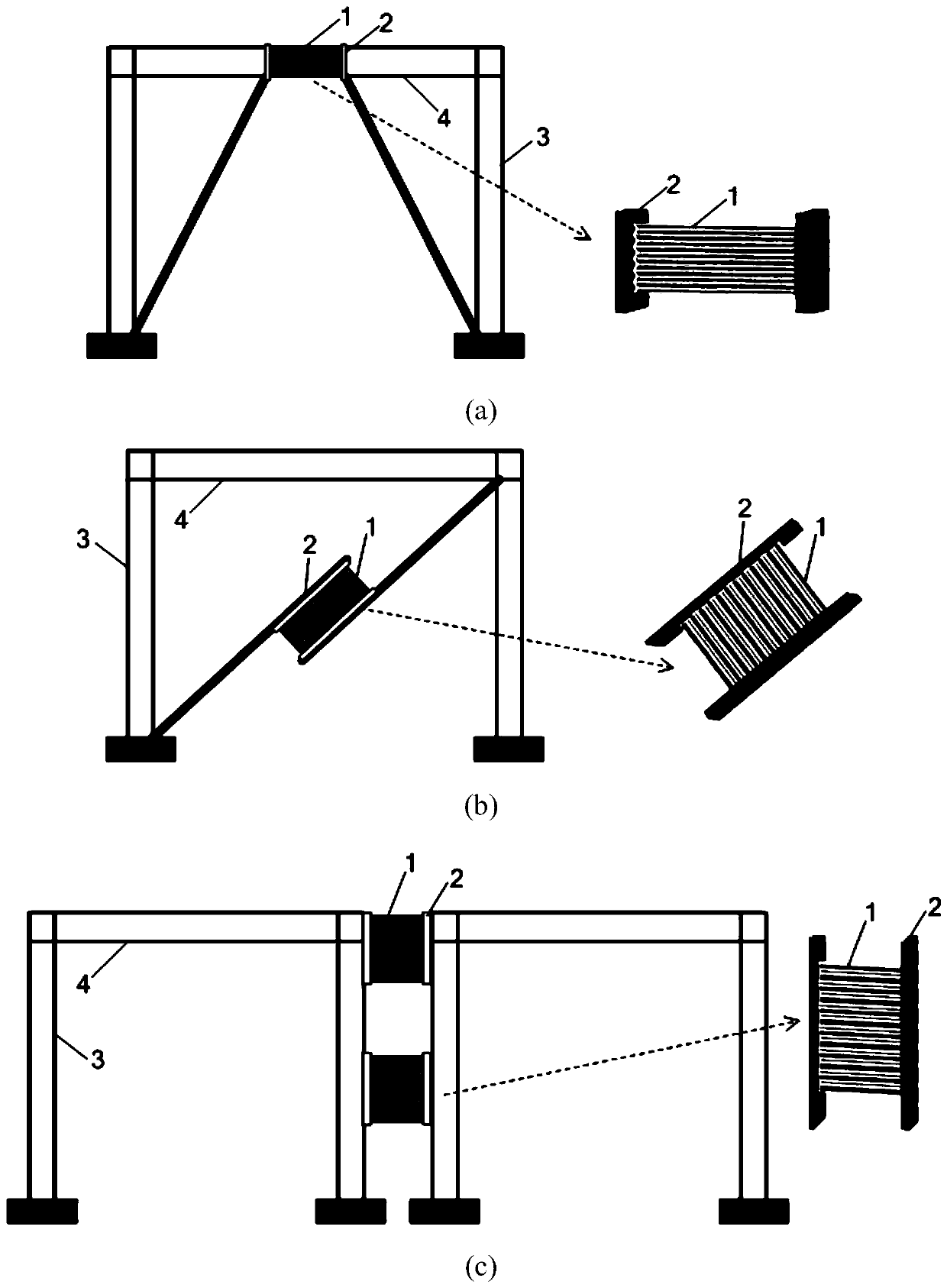
[0023] Embodiment 1: as figure 1 As shown, the present invention is a corrugated type replaceable energy dissipation device with controllable performance, which is mainly composed of corrugated steel plate 1 and connecting plate 2. Energy-dissipating beam sections, energy-dissipating supports of steel-supported frame systems, and between steel columns of steel-column steel frame systems, etc. The corrugated steel plate 1 is rolled in a factory, and the corrugated steel plate 1 and two connecting plates 2 are welded and connected. The corrugated steel plate 1 maintains elasticity under frequent earthquakes, and yields and consumes energy under fortification earthquakes and rare earthquakes.

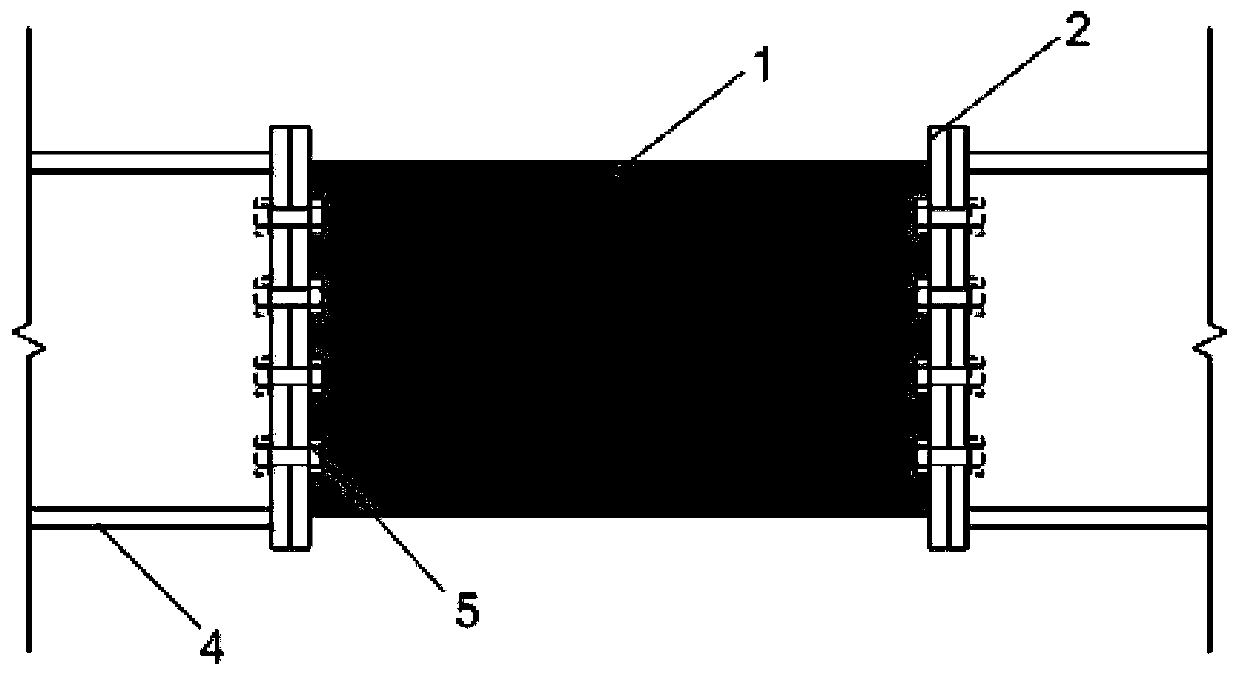
[0024] Further, such as figure 2 As shown, after the corrugated steel plate 1 and the connecting plate 2 are welded as a whole, they are connected with the surrounding structural members by high-strength bolts 5, which is convenient for repair and replacement after the earthquake.

[00...


PUM


Abstract

The invention belongs to the technical field of constructional engineering seismic energy dissipation, and provides a corrugated type replaceable energy dissipation device with the controllable performance. The device is mainly composed of a corrugated steel plate and two connecting plates. The corrugated steel plate is of an integrated structure, and the two ends of the corrugated steel plate arewelded to the connecting plates respectively, so that an I-shaped structure is formed. Out-plane buckling can be effectively avoided due to corrugations of the corrugated steel plate, the out-plane rigidity is improved, then, in-plane bearing capacity and rigidity degeneration are remarkably lowered, a hysteresis curve is full, and the energy dissipation capacity is improved. By changing the included angle between the connecting plates and the directions of corrugated lines, the bearing capacity and the rigidity of the corrugated steel plate can be adjusted, steel plate alignment is enhancedor weakened, and then the actual requirements of different projects for dampers can be precisely matched. Compared with the prior art, the manufacturing technology is simple, the steel plate performance is stable, installation is convenient, the device has the advantages that the energy dissipation capacity is high, the bearing capacity and rigidity are controllable, after an earthquake, the device can be replaced, and therefore the using function of the structure can be rapidly recovered, and the device can be used for improving the structure post-earthquake function restorability.

Description

technical field [0001] The invention belongs to the technical field of energy dissipation and shock absorption in construction engineering, and in particular relates to a corrugated pattern replaceable energy dissipation device with controllable performance. Background technique [0002] The traditional anti-seismic design concept takes the protection of life as the primary goal, and avoids brittle failure or even collapse of the structure under the action of an earthquake through ductile design, thereby reducing casualties. In order to achieve this anti-seismic goal, the design code allows the main lateral force members of the structure to undergo plastic deformation to dissipate the input energy of the earthquake, resulting in damage and residual deformation of the structural members. After the earthquake, the structure is difficult to repair and loses its function. Several recent earthquakes have shown once again that it is far from enough to take life safety as the goal ...

Claims


Application Information

Patent Timeline
Patent Type & Authority Applications(China)
IPC IPC(8): E04B1/98E04B1/24E04H9/02
CPCE04B1/24E04B1/98E04H9/021E04H9/024
Inventor 崔瑶王枫智田瑞鑫许肖卓
Owner DALIAN UNIV OF TECH
Why Eureka
Try Eureka