Centrifugal pulp pump

A slurry and pump casing technology, which is applied in the combined structure of centrifugal pump impeller and shaft seal, can solve the problems of rubber lip ring wear, rapid temperature rise of fluid and sealing components, poor fluid fluidity, etc., to reduce impact and friction, improve Operational safety, effect of lowering fluid temperature

Pending Publication Date: 2020-05-08
宜兴市宙斯泵业有限公司
View PDF2 Cites 2 Cited by
  • Summary
  • Abstract
  • Description
  • Claims
  • Application Information

AI Technical Summary

Problems solved by technology

These shaft seals all have the following disadvantages: when they are purely mechanical seals that drive the static ring, there will be gaps on the mechanical friction surface when the pump has pulse vibrations; when the pump chamber is in a positive pressure environment, fluid particles will enter the mechanical The friction surface will accelerate wear; when the lip ring and mechanical seal are combined, the pressure of the sealing part will increase, which will cause the rubber lip ring at the front end to wear faster, and then cause the particles in the fluid to enter the sealing surface of the mechanical seal at the rear end, making the The mirror surface of the moving ring and static ring of the mechanical seal of the centrifugal pump is worn and damaged;
[0007] However, the above-mentioned improved technology still has the following deficiencies: First, although the fluid at the sealing part can form a high negative pressure field, due to the poor fluidity of the fluid, the reason for the poor fluidity is that the liquid-containing chamber formed by the impeller and the pump casing is a nearly closed chamber. body, the liquid in it cannot circulate and take away the heat, resulting in rapid temperature rise due to the rotational friction between the fluid and the sealing components, causing damage to lip-shaped rubber seal rings, mechanical seal moving rings and other components due to temperature rise
Not only that, the local fluid temperature rise will also cause the plastic parts of the pump casing and impeller to swell and damage

Method used


Image

  • Centrifugal pulp pump
  • Centrifugal pulp pump
  • Centrifugal pulp pump

Examples


Embodiment 1

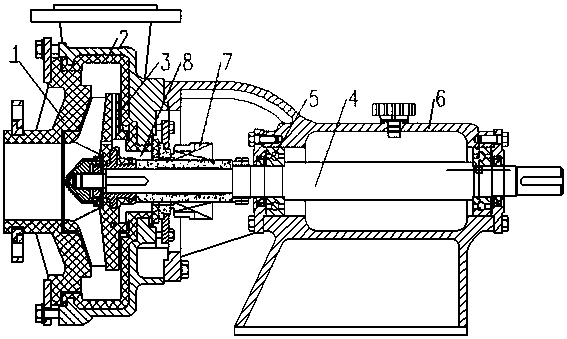
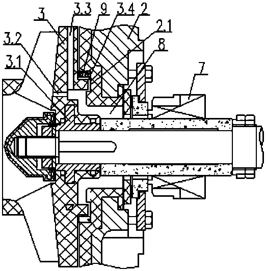
[0032] Embodiment 1: as figure 1 , 2 As shown, a centrifugal slurry pump includes a pump casing 2, a pump cover 1, a bearing 5 and a bearing bracket 6, a main shaft 4, an impeller 3, and a shaft seal 7 in the pump casing 2, the shaft seal 7 is a mechanical seal, and the impeller 3 It is a semi-open impeller with a mouth ring. The impeller 3 includes the impeller web 3.1, the impeller blade 3.7 on the front of the impeller web 3.5, and several decompression channels are opened radially from the outer side wall to the inner side of the impeller web 3.1. 3.3, the back of the impeller panel 3.5 is convexly arranged with the inner surface of the pump casing 2, specifically, the back of the impeller panel 3.5 is provided with an annular convex portion 9, and the corresponding inner wall of the pump casing 2 is provided with a matching annular concave portion 2.1, so that The back of the impeller web 3.1 is surrounded by the inner wall of the pump casing 2, the front end of the shaf...

Embodiment 2

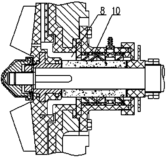
[0033] Embodiment 2: as image 3 As shown, other features remain unchanged, the impeller 3 is an open impeller, and the shaft seal 10 is a plurality of lip-shaped sealing rings.

Embodiment 3

[0034] Embodiment 3: as Figure 4 , 5 , 6, other features remain unchanged, the impeller 3 is a closed impeller, the shaft seal 7 is an assembly of the front lip seal and the mechanical seal, the impeller 3 is made of metal, and the decompression in the web 3.5 of the metal impeller The processing of flow channel 3.3 is to process radial grooves on the impeller panel 3.1 first, and then cover the impeller panel with a convex ring cover plate 3.6. After being strengthened with fasteners, it becomes the impeller panel with built-in radiation. Through-hole metal impeller, this impeller can also effectively isolate the liquid in the cavity from the pump cavity, make the sealing part form a negative pressure, and make the fluid in the sealing part circulate and replace, reducing the temperature.


PUM


Abstract

The invention discloses a centrifugal pulp pump which comprises a pump shell, a pump cover, a main shaft, an impeller and a shaft seal. The main shaft, the impeller and the shaft seal are arranged inthe pump shell. The impeller comprises an impeller center plate and an impeller blade arranged on the front face of the impeller center plate. Multiple pressure reducing runners are arranged in the curved surface wall thickness of the impeller center plate from the outer side wall to the inner side in the radial direction. The back face of the impeller center plate is matched with the inner surface of the pump shell in a convex-concave manner, a liquid storage cavity is defined by the back face of the impeller center plate, the inner wall of the pump shell, the front end face of the shaft sealand the outer circumferential face of the main shaft, and the pressure reducing runners communicate with the liquid storage cavity and an inner cavity of the pump shell. The pump is high in work efficiency and capable of saving energy by 5%-8%, the phenomenon that fluid of a sealing part is heated can be avoided, and the service life of the mechanical seal is long.

Description

technical field [0001] The invention relates to the field of centrifugal pumps, in particular to a combined structure of centrifugal pump impellers and shaft seals. Background technique [0002] Plastic-lined or full-plastic anti-corrosion and wear-resistant centrifugal slurry pumps are commonly used material conveying machinery in chemical, environmental protection, and smelting industries, especially anti-corrosion and wear-resistant plastic-lined (full plastic) centrifugal pumps for conveying corrosive slurry. Very versatile. [0003] Commonly used shaft seals for anti-corrosion slurry pumps in the prior art include mechanical seals that drive static rings or hydrodynamic seals that combine rubber lip rings and mechanical seals. These shaft seals all have the following disadvantages: when they are purely mechanical seals that drive the static ring, there will be gaps on the mechanical friction surface when the pump has pulse vibrations; when the pump chamber is in a posi...

Claims


Application Information

Patent Timeline
Patent Type & Authority Applications(China)
IPC IPC(8): F04D29/22F04D29/10F04D29/12F04D7/04F04D29/02F04D29/58
CPCF04D7/04F04D29/026F04D29/106F04D29/126F04D29/2222F04D29/2261F04D29/588Y02P20/10
Inventor 蒋龙福郭丹枫蒋列峰夏鹏飞谭希平
Owner 宜兴市宙斯泵业有限公司
Why Eureka
Try Eureka