Structure for realizing ultra-high temperature heating of synchrotron radiation light source in-situ tensile CT imaging experiment

A technique of in-situ stretching and CT imaging, applied in ohmic resistance heating, material analysis using wave/particle radiation, and testing material strength by applying stable tension/pressure, which can solve problems such as inability to heat ultra-high temperature samples , to avoid damage

Inactive Publication Date: 2020-05-08
DALIAN UNIV OF TECH +2
View PDF7 Cites 6 Cited by
  • Summary
  • Abstract
  • Description
  • Claims
  • Application Information

AI Technical Summary

Problems solved by technology

[0004] The purpose of the present invention is to propose a structure for realizing ultra-high temperature heating of synchrotron radiation light source in situ stretching CT imaging experiment in view of the problem that the current synchrotron radiation in-situ testing device cannot heat ultra-high temperature samples above 1200°C. It can heat the sample from room temperature to 1800°C and at the same time ensure that the in-situ stretching device and other precision components are at room temperature

Method used


Image

  • Structure for realizing ultra-high temperature heating of synchrotron radiation light source in-situ tensile CT imaging experiment
  • Structure for realizing ultra-high temperature heating of synchrotron radiation light source in-situ tensile CT imaging experiment
  • Structure for realizing ultra-high temperature heating of synchrotron radiation light source in-situ tensile CT imaging experiment

Examples


Embodiment 1

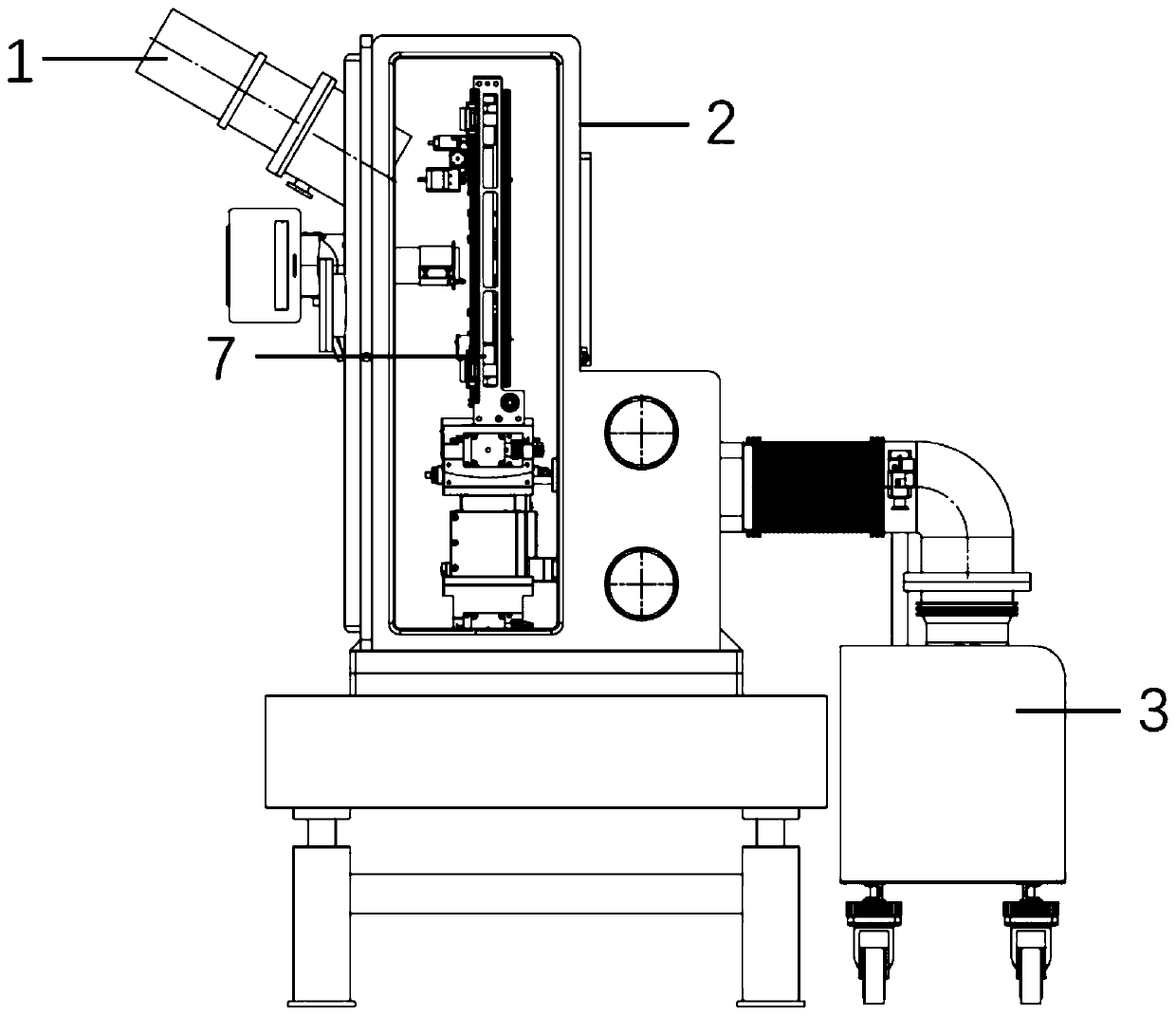
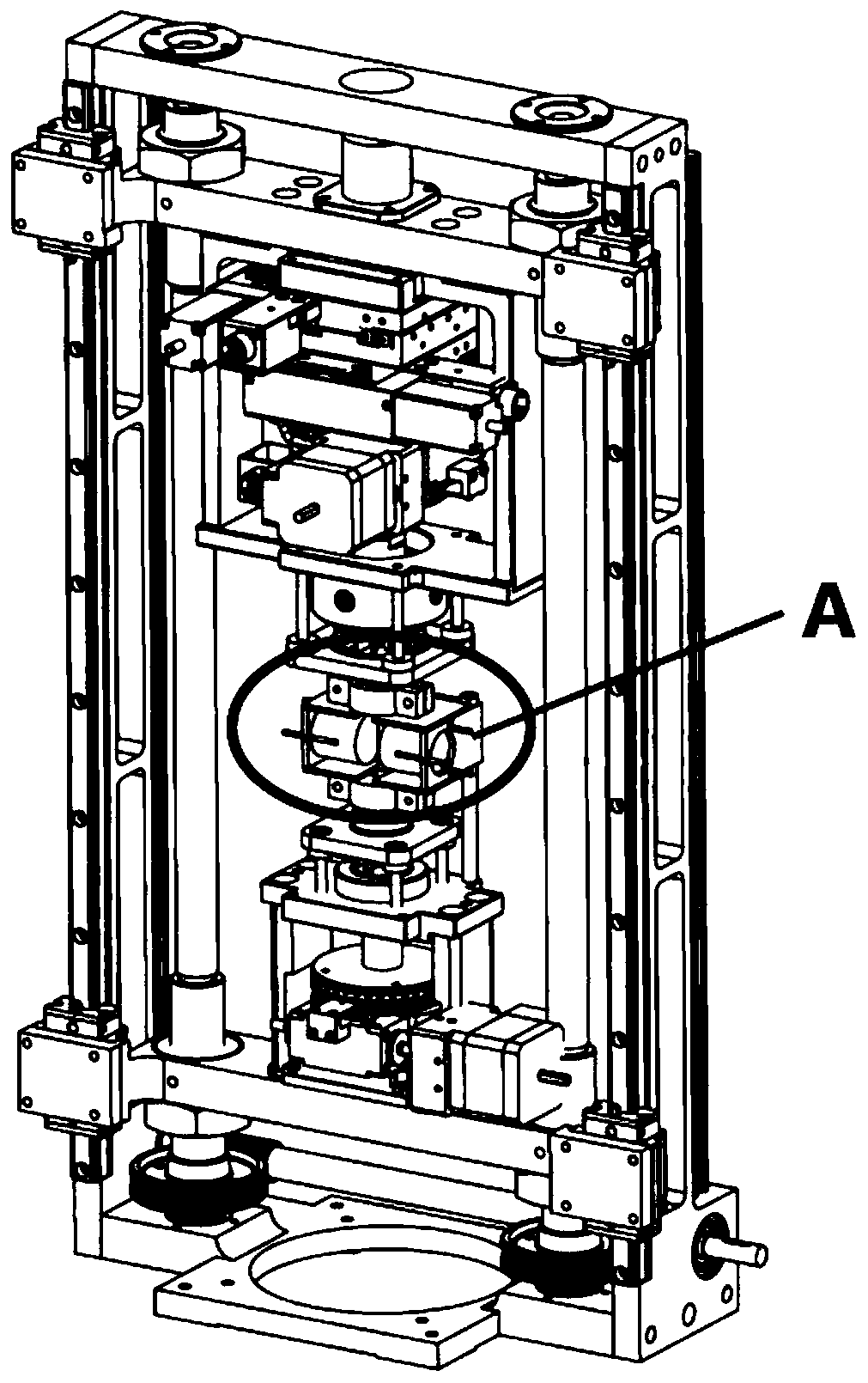
[0033] This embodiment discloses a structure for realizing ultra-high temperature heating in synchrotron radiation light source in situ stretching CT imaging experiments. The structure is as follows Figure 1-7 As shown, it includes an electron gun 1, a vacuum chamber 2, and a vacuum unit 3 connected to the vacuum chamber 2. The vacuum chamber 2 is provided with an in-situ stretching table 7. The structure of the in-situ stretching table is shown in Chinese patent 201810602634.2.

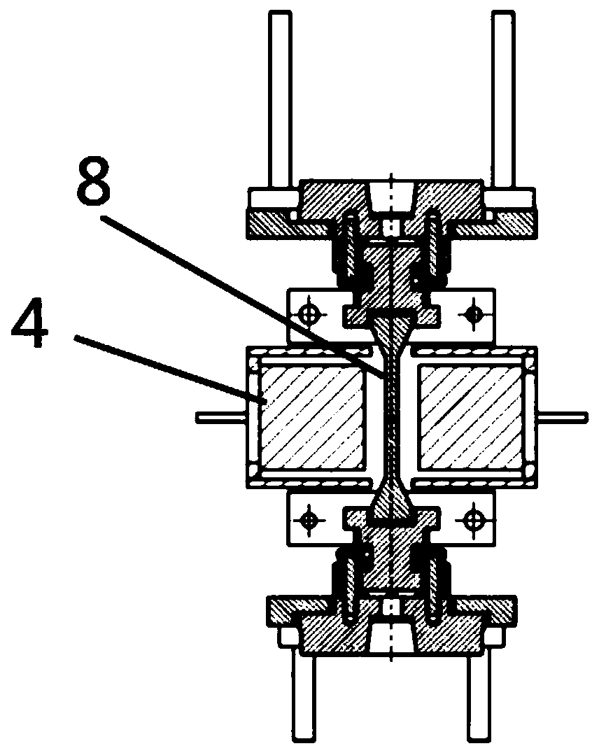
[0034] The electron gun 1 is arranged above the side wall of the vacuum chamber 2 and communicates with it, and the electron beam emitted by the electron gun can bombard the sample 8 on the in-situ stretching table; A heater 4 is arranged on the side, and a heat insulation structure is arranged between the rotating shaft of the in-situ stretching table 7 and the clamp; the rotating shaft of the in-situ stretching table 7 is covered with a cooling device.

[0035] The vacuum unit 3 communicates with ...

Embodiment 2

[0045] This embodiment discloses a synchrotron radiation in-situ stretching test bench, which includes the ultra-high temperature heating structure for realizing the in-situ stretching CT imaging experiment of a synchrotron radiation light source as described in Embodiment 1.


PUM


Abstract

The invention provides a structure for realizing ultra-high temperature heating of a synchrotron radiation light source in-situ tensile CT imaging experiment. The structure comprises an electron gun,a vacuum chamber and a vacuum unit communicated with the vacuum chamber. An in-situ stretching table is arranged in the vacuum chamber, the electron gun is arranged above the side wall of the vacuum chamber and communicated with the vacuum chamber, and electron beams emitted by the electron gun can bombard a sample on the in-situ stretching table. Heaters are arranged on the two sides of the sample on the in-situ stretching table, and a heat insulation structure is arranged between the rotating shaft of the in-situ stretching table and the clamp. The in-situ stretching table rotating shaft iscoated with a cooling device. The structure can heat the sample to room temperature to 1800 DEG C, and ensure that the in-situ stretching device and other precision parts are in a room temperature state.

Description

technical field [0001] The invention relates to heating technology, in particular to a structure for realizing ultra-high temperature heating in in situ stretching CT imaging experiments of synchrotron radiation light sources. Background technique [0002] Synchrotron radiation light source is one of the large scientific devices that the world's scientific and technological powers attach great importance to. Synchrotron radiation light has the advantages of high brightness, high coherence, and high penetrating ability, and has become a powerful probe for detecting the microstructure of matter and its evolution law. CT imaging is an important application of synchrotron radiation. This technology can non-destructively analyze the different microstructures inside materials, and has important applications in archaeology, geology, materials and other fields. When it is necessary to use synchrotron radiation CT imaging technology to study the microstructure evolution of matter in ...

Claims


Application Information

Patent Timeline
IPC IPC(8): G01N3/18G01N3/02G01N3/06G01N23/046H05B3/00H01J37/24
CPCG01N3/18G01N3/02G01N3/068G01N23/046H05B3/00H01J37/242G01N2203/0017G01N2203/0226G01N2203/0641Y02B30/00
Inventor 王同敏范国华康慧君郭恩宇陈宗宁徐宇杰
Owner DALIAN UNIV OF TECH
Why Eureka
Try Eureka