[0029] Hereinafter, the present invention will be described clearly and completely with reference to the accompanying drawings in the present invention.
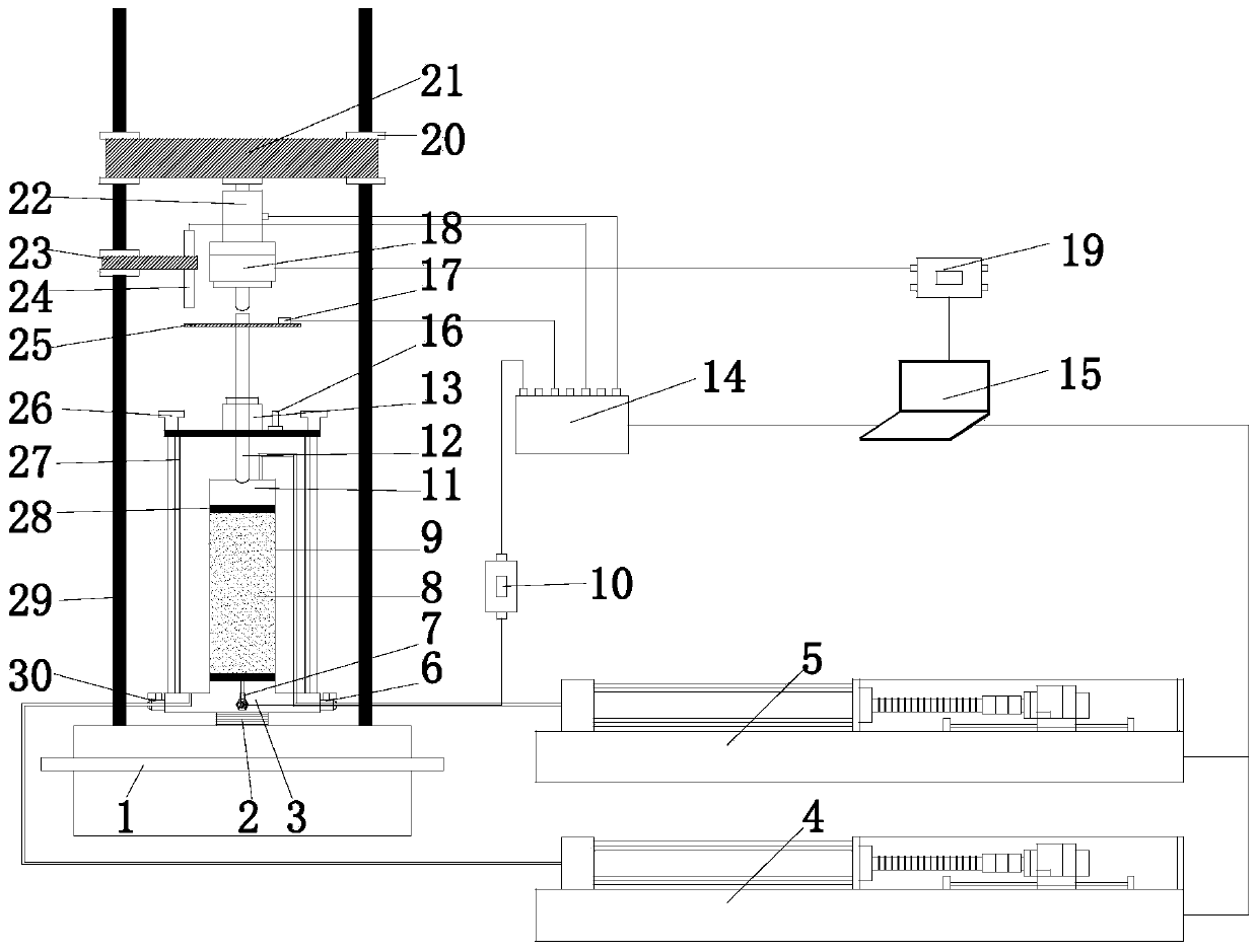
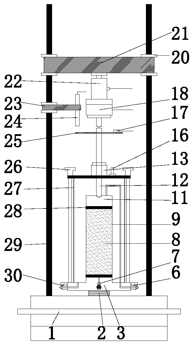
[0030] The present invention provides a triaxial instrument for synchronous loading of high-frequency cyclic loads under static load. Compared with traditional instruments, the load frequency range of the triaxial instrument is 0-120 Hz, which is much higher than the 20 Hz frequency of existing instruments, including The following structure:
[0031] 1) Main structure, 2) Loading system, 3) Pore pressure measurement system, 4) Acceleration measurement system, 5) Axial stress measurement system, 6) Displacement measurement system
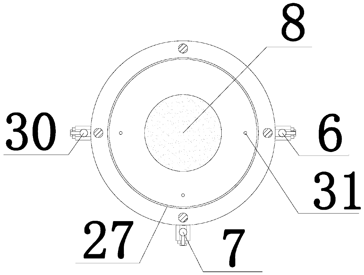
[0032] Such as figure 1 As shown, the main structure of the triaxial apparatus includes a reaction force frame 21, a loading rod 12, a pressure chamber 27, a latex film-wrapped sample 8, a pressure chamber base 3, a triaxial apparatus base 1, and a triaxial apparatus base 1. In addition to the body structure of the triaxial instrument, the reaction force stand rod 29 is also externally connected with a confining pressure controller 4, a back pressure controller 5, a pore pressure sensor 10, a high frequency collector 14, a voice coil motor driver 19, and the above components All can be controlled by the computer 15 to achieve a high degree of digitization and intelligence.
[0033] Such as Figure 2-Figure 4 As shown, the loading system includes a lifting platform 2, a voice coil motor 18 and a voice coil motor driver 19; the computer 15 is connected to the voice coil motor driver 19, the voice coil motor driver 19 is connected to the voice coil motor 18, and the voice coil motor 18 is fixed on On the high-frequency load sensor 22, the top end is connected with the reaction frame 21, and the lower part is connected with the loading rod 12. The pressure chamber 27 is fixed on the base 3 and sealed by a waterproof rubber ring 32. The pressure chamber 27 is equipped with a sample 8 for testing. The surface of the sample 8 is covered by a rubber film 9. The upper and lower ends of the rubber film 9 are respectively fixed on the pressure chamber base 3 and the sample cap 11, and the bottom end of the loading rod 12 is in contact with the sample cap 11 to pass the dynamic and static axial loads. The loading rod 12 is transferred to the sample 8.
[0034] Static loading is controlled by controlling the axial stress. The axial stress is adjusted and controlled by the computer 15 controlling the lifting of the lifting platform 2. The confining pressure is controlled by the confining pressure controller 4 to make the sample 8 reach the expected stress level, and the back pressure is controlled by The back pressure controller 5 controls to make the sample 8 reach the saturation state. The voice coil motor driver 19 controls the voice coil motor 18 to apply high-frequency vibration to the loading rod 12 and transmits it to the sample 8 to achieve the expected High frequency cyclic load loading.
[0035] The pore pressure measurement system includes a pore pressure sensor 10, which is connected to a pore pressure valve 7, which can measure the change of pore pressure in real time, and store it through a high-frequency acquisition instrument 14 and a computer 15. At the same time, in the drainage shear test, the back pressure controller 5 can obtain the body strain change of the sample 8 by measuring the drainage volume.
[0036] The acceleration measurement system includes an acceleration sensor 17. The acceleration sensor 17 fixed on the fixed frame 25 is used to measure the vibration acceleration actually transmitted to the sample 8 during the test, and is stored by the high-frequency collector 14 and the computer 15.
[0037] The axial stress measurement system includes a high-frequency load sensor 22. The high-frequency load sensor 22 connected to the loading rod 12 is used to measure the axial stress of the loading rod 12 and is stored by the high-frequency acquisition device 14 and the computer 15.
[0038] The displacement measurement system includes a displacement sensor 24 (LVDT displacement sensor is used in this example). The displacement sensor 24 fixed on the vertical rod 29 is used to measure the relative displacement of the loading rod 12, and the real-time vibration displacement of the sample 8 during shearing can also be obtained The amount and the real-time displacement in the compression process are stored by the high-frequency acquisition instrument 14 and the computer 15.
[0039] The acceleration measurement system, the axial stress measurement system, the pore pressure measurement system, and the displacement measurement system share the same high-frequency acquisition instrument 14, which is connected to the computer 15 through an optical fiber for data storage and data processing.
[0040] During the experiment, the pressure chamber base 3 and sample 8 of different specifications (domestic standards φ39.1mm, φ61.8mm and international standards, etc.) can be replaced according to the experimental requirements. The sample 8 is covered by the rubber film 9, the upper and lower parts of the rubber film 9 The two ends are respectively fixed on the pressure chamber base 3 and the sample cap 11, the bottom end of the loading rod 12 is in contact with the sample cap 11, and the axial load is transmitted to the sample through the loading rod 12. The static load is applied by controlling the axial stress, the confining pressure and the back pressure. The control of the axial stress is realized by changing the lifting rate of the lifting platform 2 by the computer 15. The confining pressure is controlled by the confining pressure controller 4 to make the sample 8 reach the expected The stress level, the back pressure is controlled by the back pressure controller 5 to make the sample 8 reach the saturation state; the voice coil motor 18 in the loading system is controlled by the driver 19 and the computer 15 to apply the high frequency cyclic load to the sample 8, the sample 8 The pore water pressure is measured by the pore pressure sensor 10, the confining pressure is measured by the confining pressure controller 4, the back pressure is measured by the back pressure controller 5, the axial stress is measured by the high frequency load sensor 22, and the axial displacement The vibration acceleration is measured by the displacement sensor 24, and the vibration acceleration is measured by the acceleration sensor 17, and the data is recorded by the high-frequency acquisition instrument 14 and the computer 15.
[0041] The above are only the basic principles and main features of the present invention and the advantages of the present invention. It should be pointed out that for those of ordinary skill in the art, without departing from the technical principles of the present invention, several improvements and modifications can be made, and these improvements and modifications should also be regarded as the protection scope of the present invention.