Battery cell winding device and method

A winding device and cell technology, applied in circuits, electrical components, secondary batteries, etc., can solve the problems of easy deviation of the diaphragm, fluctuation of diaphragm tension, and long auxiliary time.

Pending Publication Date: 2020-05-12
GEESUN AUTOMATION TECH
View PDF0 Cites 4 Cited by
  • Summary
  • Abstract
  • Description
  • Claims
  • Application Information

AI Technical Summary

Problems solved by technology

[0003] Most of the existing winding machines adopt the disk-type transposition winding method. The winding mechanism is arranged along the edge of the disk, and the position of the winding mechanism is switched by rotation. However, this method will cause many problems, for example, wear Auxiliary actions such as diaphragm and diaphragm cutting need to wait unt

Method used


Image

  • Battery cell winding device and method
  • Battery cell winding device and method
  • Battery cell winding device and method

Examples


no. 1 example

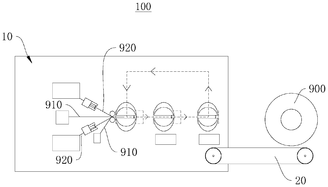
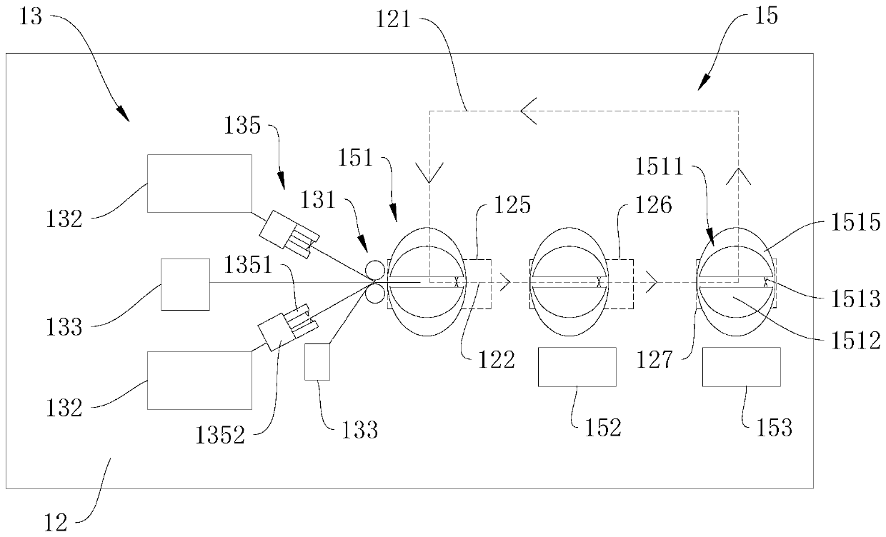
[0035] see figure 1 , figure 1 It is a schematic diagram of the structure of the cell winding device 10 applied to the cell production system 100 provided by the first embodiment of the present invention.

[0036] The first embodiment of the present invention provides a cell winding device 10, which has the characteristics of being able to continuously transport the separator 910, and having high winding efficiency and winding quality. The cell winding device 10 can be applied to a battery production device or a battery production line, etc. Of course, the cell winding device 10 can also be used independently.

[0037] Wherein, taking the cell winding device 10 applied to the battery production device as an example, the cell production system 100 includes the cell winding device 10, which is wound by the cell winding device 10 to form a winding core 900, of course, the battery The core production system 100 may also include a production transmission mechanism 20, which is di...

no. 2 example

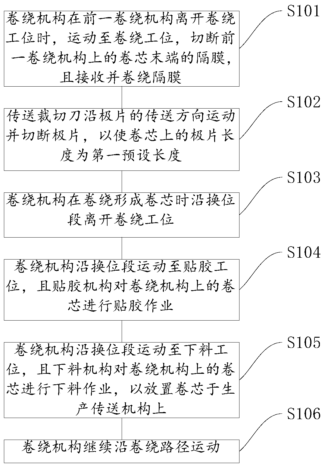
[0071] see image 3 , image 3 It is a schematic flow chart of the cell winding method provided by the second embodiment of the present invention.

[0072] The battery winding method is applied to the battery winding device 10. The basic principle and technical effects of the battery winding device 10 are the same as those of the above-mentioned embodiments. For a brief description, the parts not mentioned in this embodiment are as follows: Reference may be made to the corresponding content in the foregoing embodiments.

[0073] The cell winding method includes:

[0074] Step S101: the winding mechanism 151 moves to the winding station 125 when the previous winding mechanism 151 leaves the winding station 125, cuts off the diaphragm 910 at the end of the winding core 900 on the previous winding mechanism 151, and receives and The membrane 910 is wound.

[0075] In this way, after the previous winding mechanism 151 winds to form the winding core 900 and leaves the winding s...


PUM


Abstract

The invention discloses a battery cell winding device and method, and relates to the technical field of battery cell winding. The battery cell winding device comprises a mounting platform, a conveyingassembly and a plurality of winding mechanisms, wherein an annular winding path is arranged on the mounting platform; the winding path is provided with a transposition section which is arranged alonga straight line and provided with a winding station at one end; the conveying assembly is mounted on the mounting platform; a diaphragm conveying device is used for conveying diaphragms and pole pieces to a winding station; the conveying direction of the conveying assembly and the extending direction of the end, away from the winding station, of a transposition section are the same in direction and collinear. Multiple winding mechanisms are movably connected to the mounting platform and can move along the winding path, and the winding mechanisms can enter the winding station when the previouswinding mechanism leaves the winding station along the transposition section, the diaphragm is cut at the tail end of the winding core, the diaphragm is received and wound, and the formed winding core leaves the winding station along the transposition section when the winding core is formed. The battery cell winding device and the battery cell winding method have the characteristics that the diaphragm can be continuously conveyed, and the winding efficiency and the winding quality are higher.

Description

technical field [0001] The present invention relates to the technical field of battery winding, in particular to a battery winding device and method. Background technique [0002] In the production process of lithium battery winding machine, the completion of a winding core includes normal winding actions and auxiliary actions. The auxiliary actions generally include actions such as diaphragm penetration, diaphragm cutting, and glue cutting. The auxiliary actions before and after normal winding are The main component of the entire winding process of the battery core, the length of the auxiliary time corresponding to the auxiliary action directly affects the efficiency of the entire equipment. [0003] Most of the existing winding machines adopt the disk-type transposition winding method. The winding mechanism is arranged along the edge of the disk, and the position of the winding mechanism is switched by rotation. However, this method will cause many problems, such as wear a...

Claims


Application Information

Patent Timeline
IPC IPC(8): H01M10/0587H01M10/04
CPCH01M10/0409H01M10/0587Y02E60/10Y02P70/50
Inventor 阳如坤杨吉陈飞李灵聪魏宏生
Owner GEESUN AUTOMATION TECH
Why Eureka
Try Eureka