Waste incineration flue gas spraying deacidification tower

A technology of leaching deacidification tower and waste incineration, which is applied in gas treatment, dispersed particle separation, membrane technology and other directions, can solve the problems of increasing the volume of the spray tower, increasing the floor space, and increasing the cost of use, and achieves reliability and service life. The effect of improving cycle, improving cleanliness and good purification effect

Pending Publication Date: 2020-05-15
云南净美环保科技有限公司
View PDF0 Cites 2 Cited by
  • Summary
  • Abstract
  • Description
  • Claims
  • Application Information

AI Technical Summary

Problems solved by technology

This method will increase the volume of the spray tower (increase the floor area or increase the height), increase the manufacturing cost caused by the larger purification liquid supply and regeneration treatment facilities, and the purification liquid supply required to process the unit volume of flue gas Negative effects such as increased use costs caused by increased pump power consumption

Method used


Image

  • Waste incineration flue gas spraying deacidification tower
  • Waste incineration flue gas spraying deacidification tower
  • Waste incineration flue gas spraying deacidification tower

Examples


Embodiment 1

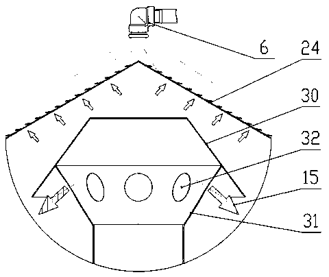
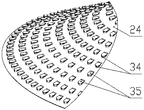
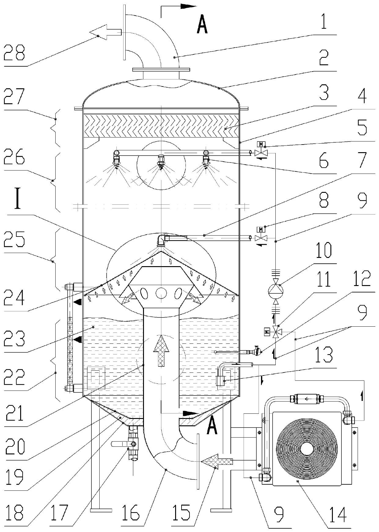
[0054] Such as figure 1 as shown, figure 1 It is a structural schematic diagram of an embodiment of the structure of a garbage incineration flue gas spray deacidification tower provided by the present invention, combined with figure 2 , image 3 ,in, figure 2 for figure 1 A-A in the sectional view further shows the structure of the present invention; image 3 for figure 1 The partial enlarged view of the I place shows the structure of the foaming section (25) in the tower and the flow characteristics of the gas flow at this position.

[0055] The structure of the waste incineration flue gas spray deacidification tower includes a tower tube 4, the top of the tower tube 4 is provided with an upper head 2, the bottom is provided with a lower head 18, and the outside is provided with a spray pipe Road system 9; an exhaust pipe 1 is provided above the upper head 1, and an air intake pipe 16 is provided below the lower head 18;

[0056] The interior of the tower 4 is provid...

Embodiment 2

[0077] Such as Image 6 as shown, Image 6 It is a structural schematic diagram of another embodiment of the structure of a waste incineration flue gas spray deacidification tower provided by the present invention.

[0078] The differences between this embodiment and Embodiment 1 are:

[0079] 1) Structurally, the three-way valve 11 in Embodiment 1 is cancelled, and the spray liquid intake port 13 is directly connected to the spray pump 10; the tower 4 corresponding to the liquid storage area 22 is also provided with a cooling liquid intake Port 36 and liquid return port 39, the heat dissipation liquid intake port 36 and liquid return port 39 are all installed on the side wall of the tower tube 4, and pass through the side wall of the tower tube 4 to the outside and pass through the heat dissipation pipeline system 37 connected; the heat dissipation pipeline system 37 is provided with a heat dissipation pump 38 and a heat dissipation system 14 in series; that is, the spray p...


PUM


Abstract

The invention discloses a waste incineration flue gas spraying deacidification tower. The top of a tower barrel is provided with an upper sealing head with an exhaust pipe, the bottom of the tower barrel is provided with a lower sealing head with an air inlet pipe, the side wall of the tower barrel is provided with a spraying liquid taking opening, and the exterior of the tower barrel is providedwith a spraying pipeline system; an ascending pipe communicated with the air inlet pipe is arranged in the tower barrel, an air distribution cone is arranged at the upper end of the ascending pipe, abaffling cap is arranged at the top of the air distribution cone, and a foam generation cover, a liquid distribution system, a defoaming system and a demister are sequentially arranged above the baffling cap from bottom to top. Flue gas flows in the tower from bottom to top, a purification liquid flows from top to bottom, when the flue gas and the purification liquid are in contact with each otherin the foam generation cover, foam is generated, the flue gas is promoted to be in full contact with the purification liquid, then the dynamic stability of the foam is maintained, and finally the flue gas is exhausted after being demisted. Compared with a common traditional spraying tower, the spraying deacidification tower provided by the invention is more suitable for waste incineration flue gas, has better purification effect and reliability, does not need to build a huge purification liquid treatment system, and has lower construction and operation costs.

Description

technical field [0001] The invention relates to the field of purification treatment of incineration flue gas, in particular to a waste incineration flue gas spray deacidification tower. [0002] technical background [0003] The washing process is an important means of exhaust gas purification. This process is to contact the purification liquid containing the purification agent with the exhaust gas, heat and mass transfer between the gas and liquid phases, and even a chemical reaction, to remove or reduce harmful components in the exhaust gas, so as to achieve the purpose of purifying the exhaust gas. [0004] Spraying is a kind of washing process. After the exhaust gas is passed into the spray tower, the purification liquid is boosted and sprayed out through a special nozzle to form a large number of mist droplets, so as to achieve full contact between the exhaust gas and the purification liquid mist droplets. In order to improve the spray effect, the usual measure is to in...

Claims


Application Information

Patent Timeline
IPC IPC(8): B01D53/78
CPCB01D53/78B01D2258/0291
Inventor 邹娱陈迪华刘南渠冯威旗邹辉
Owner 云南净美环保科技有限公司
Why Eureka
Try Eureka