Base material cutting and forming equipment for photovoltaic cell panel processing

A photovoltaic cell panel and forming equipment technology, applied in glass manufacturing equipment, glass cutting devices, manufacturing tools, etc., can solve the problems of photovoltaic cell panel base material deviation, influence on cutting, uneven force, etc., and achieve high cutting stability , Uniform force and strong adaptability

Inactive Publication Date: 2020-05-15
张红宾
View PDF5 Cites 3 Cited by
  • Summary
  • Abstract
  • Description
  • Claims
  • Application Information

AI Technical Summary

Problems solved by technology

[0004] Due to the existing process of manufacturing solar panel components, there is a sealing process that requires the use of tempered glass. However, before the tempered glass is used for sealing, the process of cutting the tempered glass needs to be completed. However, most equipment is performing tempered glass. When cutting, workers need to manually push the tempered glass. When pushing manually, it is easy to have uneven force, and the base material for photovoltaic panel processing will shift, which will affect the cutting process.

Method used


Image

  • Base material cutting and forming equipment for photovoltaic cell panel processing
  • Base material cutting and forming equipment for photovoltaic cell panel processing
  • Base material cutting and forming equipment for photovoltaic cell panel processing

Examples


Embodiment 1

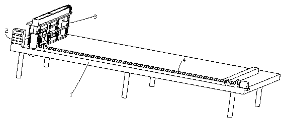
[0034] like figure 1 and figure 2 As shown, a base material cutting and forming equipment for processing photovoltaic panels in this embodiment includes a workbench 1, a control structure 2, a cutting structure 3 and a pushing structure 4, and the workbench 1 is located below the blade of the cutting motor 311 A cutting groove 11 is opened, and a control structure 2, a cutting structure 3 and a pushing structure 4 are arranged on the workbench 1. The control structure 2 is electrically connected to an external power supply, and the control structure 2 is respectively connected to the driving motor 32, the pushing motor 42, and the electric push rod. 31 is electrically connected with the cutting motor 311, and the control structure 2 and the cutting structure 3 are arranged on the right side of the pushing structure 4, and the pushing structure 4 includes a straight plate 41, a pushing motor 42, a second threaded rod 43, a T-shaped block 44, a third Threaded rod 45, push plat...

Embodiment 2

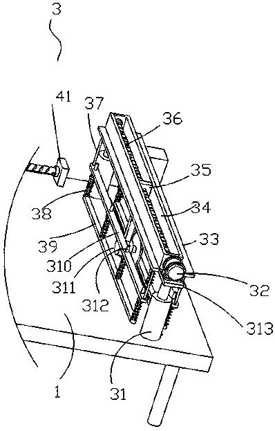
[0036] Embodiment two is a further improvement on embodiment one, as figure 1 and image 3As shown, the cutting structure 3 includes an electric push rod 31, a drive motor 32, a limit slider 35, a first threaded rod 36 and a cutting motor 311, the electric push rod 31 is fixedly connected to the workbench 1, and the top of the electric push rod 31 is fixedly connected There is a top plate 313, and the top plate 313 is fixedly connected with the drive motor 32 through a fixedly connected mounting frame. The rod 36 is fixedly connected to the output end of the drive motor 32, the first threaded rod 36 is threadedly connected with a limit slider 35 that fits and slidably connects with the limit chute 34, and the bottom of the limit slider 35 is fixedly equipped with a cutting motor 311 , the output end of the cutting motor 311 is fixedly connected with a cutting blade, and the electric push rod 31 of the cutting structure 3 drives the top plate 313 to move, and the top plate 313...

Embodiment 3

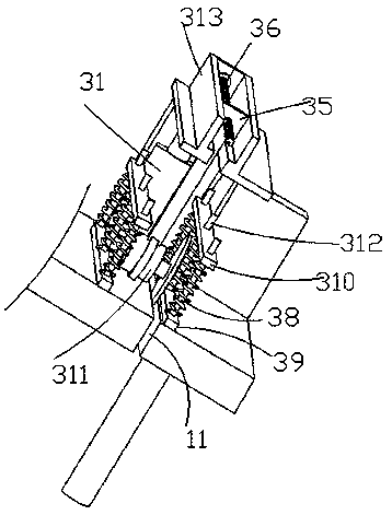
[0038] Embodiment three is a further improvement on embodiment one, as figure 1 , 3 As shown in 4, the left and right outer walls of the top plate 313 are fixedly connected with an outer plate 33, the top of the outer plate 33 is fixedly connected with a straight rod 37, the bottom of the straight rod 37 is fixedly connected with a connecting plate 310, and the bottom of the connecting plate 310 is fixedly connected with a slide bar 312 , the bottom of the slide bar 312 is fixedly connected with a pressure plate 39, and a compression spring 38 is fixedly connected between the pressure plate 39 and the connection plate 310, and the pressure plate 39, the slide bar 312 and the compression spring 310 in the cutting structure 3 cooperate with each other to facilitate the pressure plate 39 Pressing the base material processed by the photovoltaic cell panel can avoid sliding on the cutting of the base material processed by the photovoltaic cell panel, so that the cutting stability o...


PUM


Abstract

The invention relates to the technical field of photovoltaic module processing. The invention discloses base material cutting and forming equipment for photovoltaic cell panel processing. The equipment comprises a workbench. A control structure, a cutting structure and a pushing structure are arranged on the workbench. The pushing structure comprises a straight plate, the straight plate is provided with a second threaded rod, the second threaded rod is connected with a pushing motor, a sliding block is arranged on the second threaded rod, the sliding block is connected with a pushing plate, the pushing plate is connected with third threaded rods, and the third threaded rods are connected with T-shaped blocks. The cutting structure comprises an electric push rod, the electric push rod is connected with the workbench, the electric push rod is provided with a top plate, the top plate is provided with a limiting sliding groove, the limiting sliding groove is communicated with a first threaded rod, the first threaded rod is connected with a driving motor, the first threaded rod is provided with a limiting sliding block, and the limiting sliding block is provided with a cutting motor. According to the invention, the T-shaped blocks are used for pushing a photovoltaic cell panel machining base material between the two sets of T-shaped blocks to move, pushing advancing force is uniform, meanwhile, after the T-shaped blocks clamp the photovoltaic cell panel machining base material, the position of the photovoltaic cell panel machining base material cannot deviate relative to the position of the cutting motor, and actual cutting is facilitated.

Description

technical field [0001] The invention relates to the technical field of photovoltaic module processing, in particular to a base material cutting and forming equipment for processing photovoltaic panels. Background technique [0002] Solar photovoltaic cells, referred to as photovoltaic cells, are used to directly convert the sun's light energy into electrical energy. At present, silicon solar cells based on silicon are widely used in terrestrial photovoltaic systems, which can be divided into monocrystalline silicon, polycrystalline silicon, and amorphous silicon solar cells. In terms of comprehensive performance such as energy conversion efficiency and service life, monocrystalline silicon and polycrystalline silicon cells are superior to amorphous silicon cells. Polysilicon is less efficient than monocrystalline silicon, but it is cheaper. [0003] Tempered glass is safety glass. Tempered glass is actually a kind of prestressed glass. In order to improve the strength of ...

Claims


Application Information

Patent Timeline
Patent Type & Authority Applications(China)
IPC IPC(8): C03B33/027C03B33/03C03B33/037
CPCC03B33/027C03B33/03C03B33/037
Inventor 张红宾
Owner 张红宾
Why Eureka
Try Eureka