Scanning probe and preparation method thereof

A technology of scanning probes and probes, which is applied in the field of scanning probes and its preparation, can solve problems such as damage between the needle tip and the sample, large distance, and limitation of the application range of STM, and achieve excellent wear resistance and stability

Pending Publication Date: 2020-05-15
上海新克信息技术咨询有限公司
View PDF6 Cites 1 Cited by
  • Summary
  • Abstract
  • Description
  • Claims
  • Application Information

AI Technical Summary

Problems solved by technology

Usually, the height control of STM adopts the current feedback mechanism. When the needle tip of the STM scans to the insulating area, the current will decrease sharply. The electroceramic action reduces this distance, eventually causing the tip to collide with the sample causing damage
[0004] In addition, when performing STM measurement, the probe material is generally a simple metal (W) or a platinum-iridium (Pt / Ir) alloy, etc., and the sample to be tested must be a metal (or semiconductor) material; due to the impact of gas molecules on the tip The scanning process must be carried out in ultra-vacuum; in order to reduce the influence of thermal noise, the measurement is often carried out at extremely low temperature; in addition, the surface of the sample to be tested needs to be very flat to reduce the damage to the tip of the scanning probe. Greatly limit the scope of application of STM

Method used


Image

  • Scanning probe and preparation method thereof
  • Scanning probe and preparation method thereof
  • Scanning probe and preparation method thereof

Examples


Embodiment 1

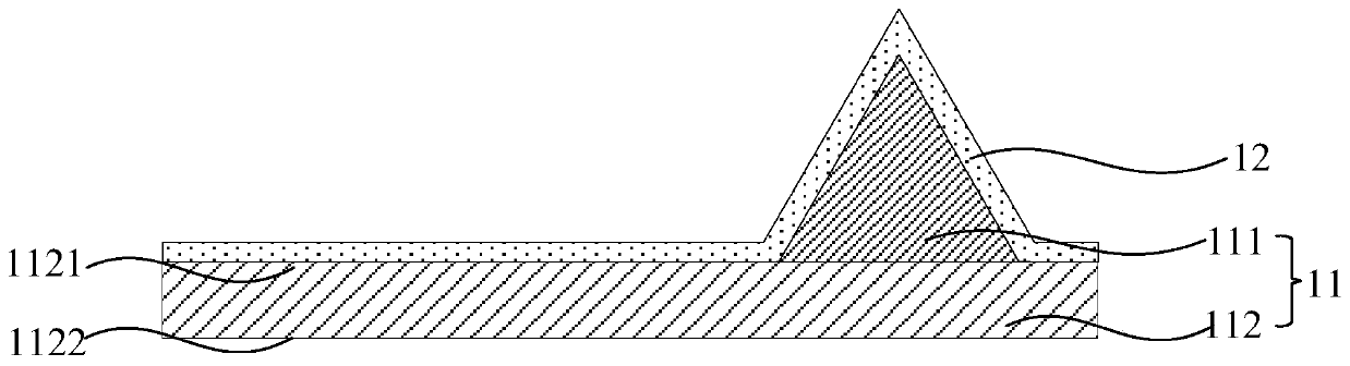
[0051] Such as Picture 9 As shown, the present invention provides a novel scanning probe. The scanning probe includes a probe body 11, which includes a needle tip 111 and a micro cantilever 112 that carries the needle tip 111. The micro cantilever 112 is provided with an upper surface 1121 and an upper surface 1121. The surface corresponds to the lower surface 1122, the tip 111 is connected to the upper surface 1121 of the microcantilever near the end; the conductive metal layer 12 covering the upper surface 1121 of the microcantilever and the tip 111; the insulating layer 13 covering the conductive metal layer 12; covering the lower surface of the microcantilever 1122 of the metal reflective layer 14.

[0052] As an example, the probe body 11 is composed of a micro cantilever 112 and a sharp tip 111 at the end of the micro cantilever. The length of the micro cantilever includes 100 to 500 μm, the width includes 5 to 20 μm, and the thickness includes 500 nm to 5 μm. The material...

Embodiment 2

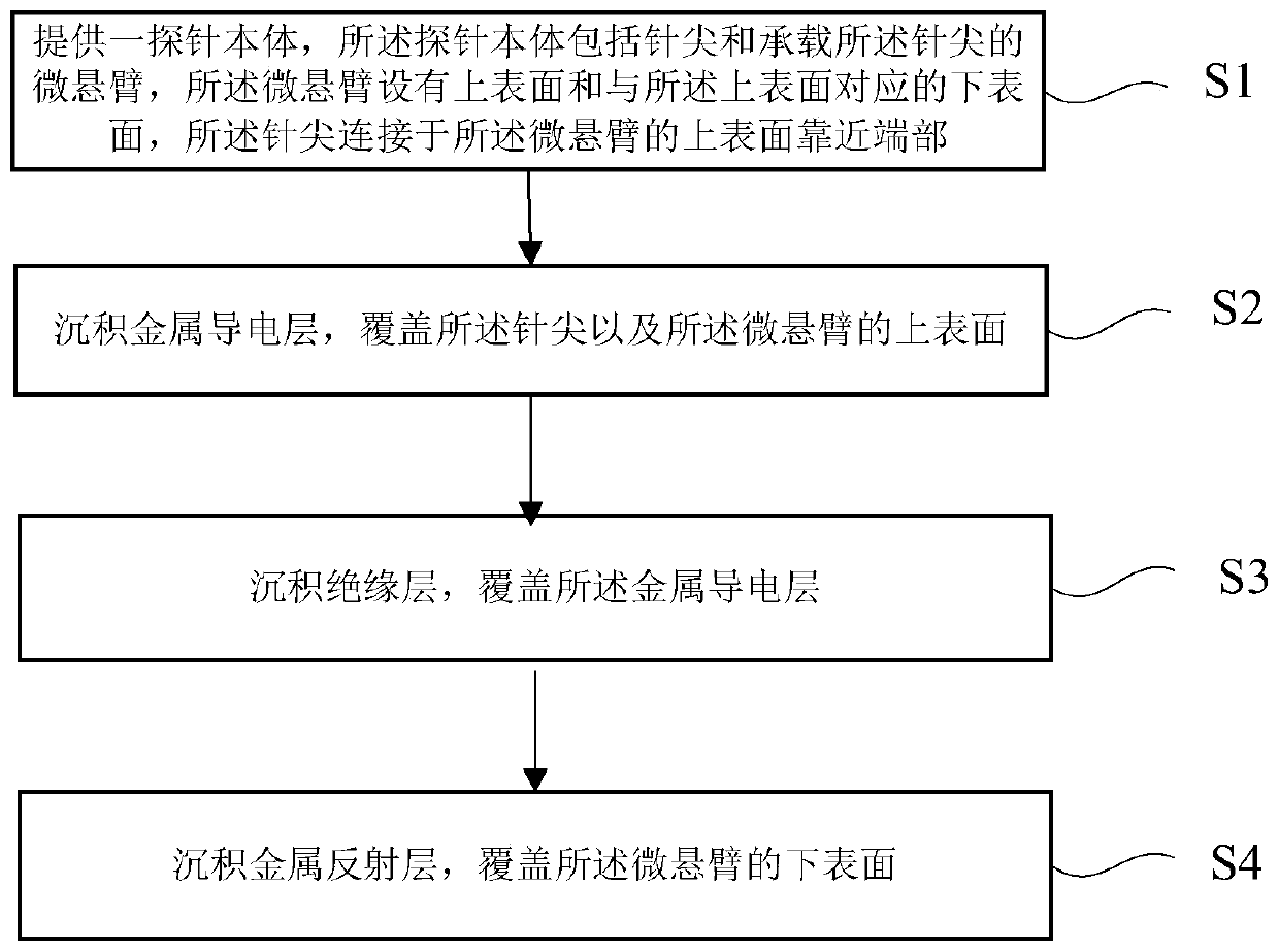
[0059] Please refer to figure 1 , The present invention provides a method for preparing a novel probe, the method for preparing the novel probe includes the following steps:

[0060] 1) A probe body is provided. The probe body includes a needle tip and a micro cantilever carrying the needle tip. The micro cantilever is provided with an upper surface and a lower surface corresponding to the upper surface. The needle tip is connected to the The upper surface of the micro cantilever is close to the end;

[0061] 2) Depositing a first conductive metal layer, which covers the tip and the upper surface of the microcantilever;

[0062] 3) Depositing an insulating layer to cover the first metal conductive layer;

[0063] 4) Depositing a metal reflective layer to cover the lower surface of the microcantilever.

[0064] Combine the attachment below Figure 2 to 9 The technical solution of this embodiment is described in detail.

[0065] Such as figure 2 As shown, step 1) is performed to provide...


PUM

PropertyMeasurementUnit
Lengthaaaaaaaaaa
Widthaaaaaaaaaa
Thicknessaaaaaaaaaa

Abstract

The invention provides a novel scanning probe for a novel scanning tunneling microscope and a preparation method thereof. The scanning probe comprises a probe body. The probe body comprises a probe tip and a micro-cantilever bearing the probe tip, the micro-cantilever being provided with an upper surface and a lower surface corresponding to the upper surface, and the probe tip being connected to the position, close to the end, of the upper surface of the micro-cantilever; a metal conductive layer covering the upper surface of the micro-cantilever and the probe tip; an insulating layer coveringthe metal conductive layer; and a metal reflecting layer covering the lower surface of the micro-cantilever. The novel scanning probe is formed by introducing the insulating layer, feedback control over whether the scanning probe makes contact with a sample or not, the contact distance and the like can be achieved through atomic force, and the application field of the scanning tunneling microscope is widened.

Description

Technical field [0001] The invention belongs to the field of measurement and detection equipment, and particularly relates to a scanning probe and a preparation method thereof. Background technique [0002] In recent years, with the development of condensed matter physics, many quantum materials have been found to have very interesting unconventional boundary states, such as quantum Hall effect, quantum anomalous Hall effect, quantum spin Hall effect, and two-dimensional quantum topological insulators, etc. . People usually place these research objects with boundary states on a conductive substrate for measurement, but this kind of measurement is indirect. It is easily affected by the conductive substrate and may also adsorb things on the boundary; in addition, due to these new types All materials have a small energy band gap, and good experimental results can only be measured under low temperature and strong magnetic field conditions. Therefore, the measurement process is more ...

Claims


Application Information

Patent Timeline
IPC IPC(8): G01Q60/16
CPCG01Q60/16
Inventor 孙秋娟周义欣王慧山
Owner 上海新克信息技术咨询有限公司
Why Eureka
Try Eureka