Comprehensive treatment device for dust-containing waste gas

A comprehensive treatment and exhaust gas technology, which is applied in the direction of combined devices, dispersed particle separation, chemical instruments and methods, etc., can solve the problems that the treatment equipment cannot achieve the treatment effect, the dust removal is insufficient, the treatment equipment is blocked, etc., and the utilization rate is disclosed. , save water, and capture high-efficiency effects

Active Publication Date: 2020-05-19
广西盛隆钢铁材料研究院有限公司
View PDF5 Cites 4 Cited by
  • Summary
  • Abstract
  • Description
  • Claims
  • Application Information

AI Technical Summary

Problems solved by technology

Due to the variety of waste gas production situations, many waste gases will contain more dust particles when they are generated. After such waste gas enters the treatment equipment, it will cause blockage and coverage of the treatment equipment after a long period of operation, making the original treatment equipment unable to meet the requirements. Therefore, it is necessary to carry out dust removal work on the exhaust gas containing dust;
[0003] The prior art has the following deficiencies: in the prior art, the treatment of dust in the exhaust gas generally adopts methods such as spraying or bagging to remove dust, but only by a separate bag or spraying dust, the removal of dust is not sufficient, and In the bag dust removal, the bag needs to be cleaned frequently, and the spray tower causes a lot of waste of water resources. Therefore, there is an urgent need for a comprehensive treatment device for dust-containing waste gas that is sufficient to remove dust, economical and environmentally friendly to solve the above problems.

Method used


Image

  • Comprehensive treatment device for dust-containing waste gas
  • Comprehensive treatment device for dust-containing waste gas
  • Comprehensive treatment device for dust-containing waste gas

Examples


Embodiment Construction

[0032] The implementation mode of the present invention is illustrated by specific specific examples below, and those who are familiar with this technology can easily understand other advantages and effects of the present invention from the contents disclosed in this description. Obviously, the described embodiments are a part of the present invention. , but not all examples. Based on the embodiments of the present invention, all other embodiments obtained by persons of ordinary skill in the art without making creative efforts belong to the protection scope of the present invention.

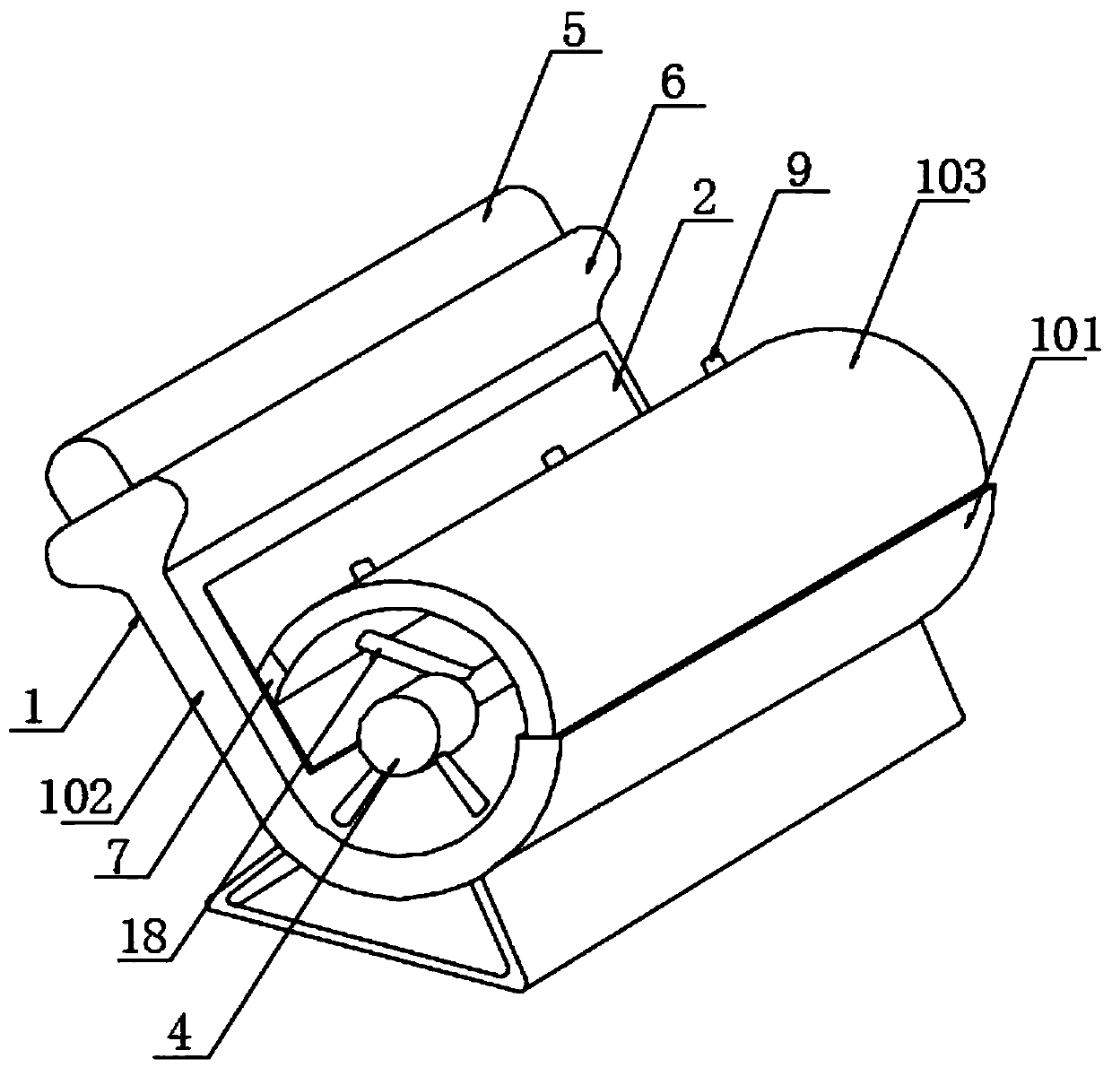
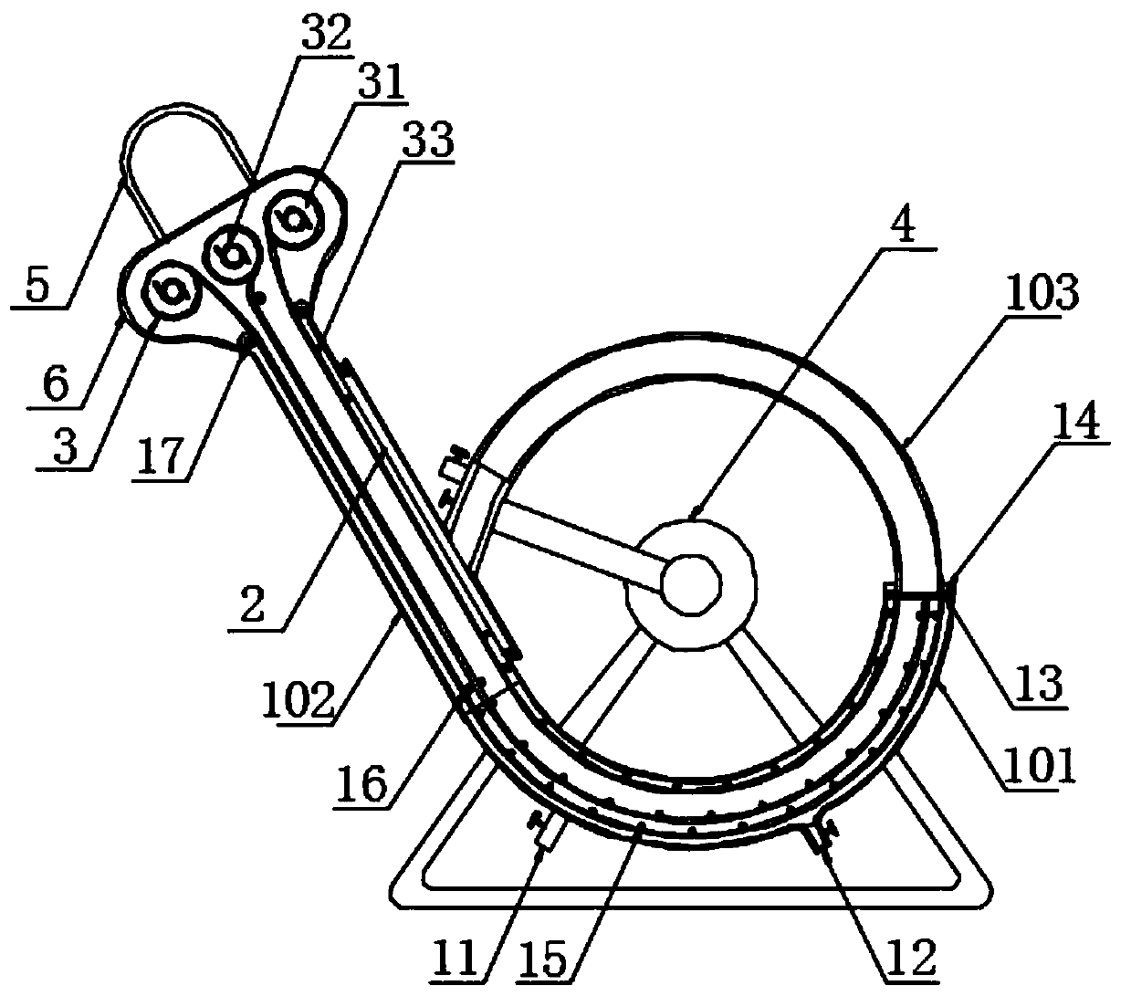
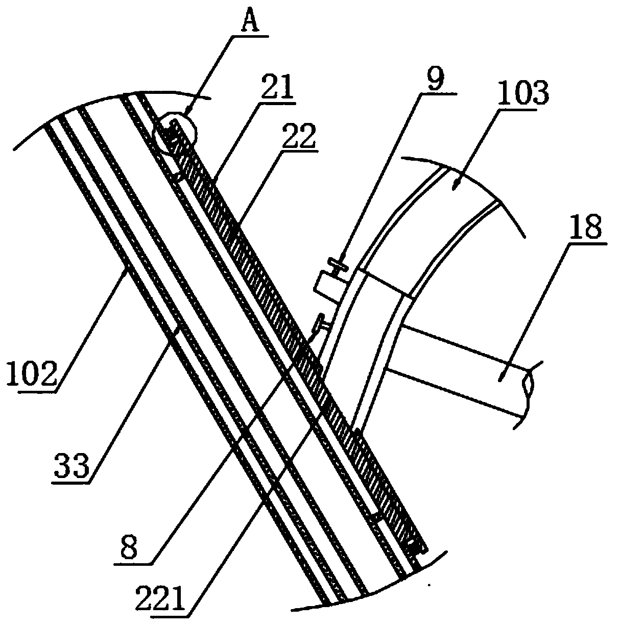
[0033] Refer to the attached Figure 1-4 , a comprehensive treatment device for dust-containing waste gas in this embodiment includes a body 1, the bottom of which is fixed with a base, and the body 1 is composed of an intermediate water tank 101, an intake filter box 102 and a telescopic box 103 connected to each other. A hollow box with a "6" cross-section, the intake filter box 102 is fixed on ...


PUM


Abstract

The embodiment of the invention discloses a comprehensive treatment device for dust-containing waste gas. The invention relates to the field of waste gas treatment devices. The comprehensive treatmentdevice comprises a machine body, a base is fixedly arranged at the bottom of the machine body;the machine body is a hollow box body with a 6-shaped cross section, which is formed by communicating a middle water tank, an air inlet filter box and a telescopic box; wherein the air inlet filter box is fixedly arranged at the top of one end of the middle water tank, the telescopic box is arranged at the other end of the middle water tank and is driven by aservo motor to slide back and forth in the middle water tank, the top end of the air inlet filter box is integrally connected with a winding box, the top end of the winding box is communicated with an air inlet box, and a winding mechanism is arranged in the winding box. According to the whole comprehensive treatment device, double dust catching can be conducted throughdust catching cloth and water, humidified and filtered moisture and newly-entering gas are mixed through backflow, dust catching is efficient, water flowing is achieved through continuously-ventilated pressure, the dust catching cloth is flushed, and the high dust catching effect is guaranteed.

Description

technical field [0001] The embodiments of the present invention relate to the field of waste gas treatment devices, in particular to comprehensive treatment devices for dust-containing waste gas. Background technique [0002] Waste gas purification mainly refers to the work of treating industrial waste gas generated in industrial places, such as dust particles, flue gas smoke, odorous gas, and toxic and harmful gases. Common waste gas purification includes factory smoke and dust waste gas purification, workshop dust waste gas purification, organic waste gas purification, acid and alkali waste gas purification, chemical waste gas purification and odor deodorization purification, etc. Due to the variety of waste gas production situations, many waste gases will contain more dust particles when they are generated. After such waste gas enters the treatment equipment, it will cause blockage and coverage of the treatment equipment after a long period of operation, making the origin...

Claims


Application Information

Patent Timeline
Patent Type & Authority Applications(China)
IPC IPC(8): B01D50/00
CPCB01D50/60
Inventor 不公告发明人
Owner 广西盛隆钢铁材料研究院有限公司
Why Eureka
Try Eureka