Light material separation device

A separation device and material technology, applied in the direction of solid separation, separation of solids from solids with airflow, recycling of construction waste, etc., can solve the problems of high labor costs, inability to separate accurately, time-consuming and labor-consuming, etc., to reduce dust Pollution and noise pollution, avoid scattering, improve the effect of sorting

Inactive Publication Date: 2020-05-19
义乌市铭耀智能科技有限公司
View PDF0 Cites 1 Cited by
  • Summary
  • Abstract
  • Description
  • Claims
  • Application Information

AI Technical Summary

Problems solved by technology

[0002] With the acceleration of urbanization in our country, the process of urban renewal is accompanied by a large number of building demolition and demolition, resulting in a large amount of construction waste. If it is not handled properly, it will cause environmental pollution and waste of resources. The construction waste after building demolition and demolition is often mixed Decoration waste, construction waste is mostly heavy materials such as concrete blocks, crushed stones, bricks and tiles, and decoration waste is mostly light materials such as gypsum board, wallpaper, plastic, cloth art, etc. All kinds of waste are mixed together for waste disposal and the inconvenience of reuse
At present, manual sorting, water selection and winnowing are mostly used for sorting construction waste. Although manual sorting is accurate, it is time-consuming and labor-intensive, with extremely low efficiency and high labor costs; water sorting is based on the density of materials. With the help of the buoyancy of water, the low-density ones float on the water surface, and the high-density ones sink into the water and are separated on the conveyor belt to achieve sorting. Although the separation effect of water separation is good, it will generate a lot of sewage, and a lot of money will be invested in the follow-up. The compressed mud cake can no longer be used due to the addition of chemicals, which will pollute the environment and waste resources, which violates the concept of environmental protection. In addition, during the water selection process, materials with the same density as water will be suspended in the water , cannot be effectively separated, and materials of water-absorbing materials cannot be separated accurately; winnowing is to use wind force to separate light materials from heavy materials, and use light materials and heavy materials to move at different speeds and trajectories under the action of wind force To achieve separation, because after the construction waste is crushed, the light materials and heavy materials are mixed together and squeezed each other. The gap between the materials is too small, and the heavy materials often hinder the wind and movement of the light materials. , so relying solely on wind power for sorting, the sorting effect is not ideal

Method used


Image

  • Light material separation device
  • Light material separation device
  • Light material separation device

Examples


Embodiment 1

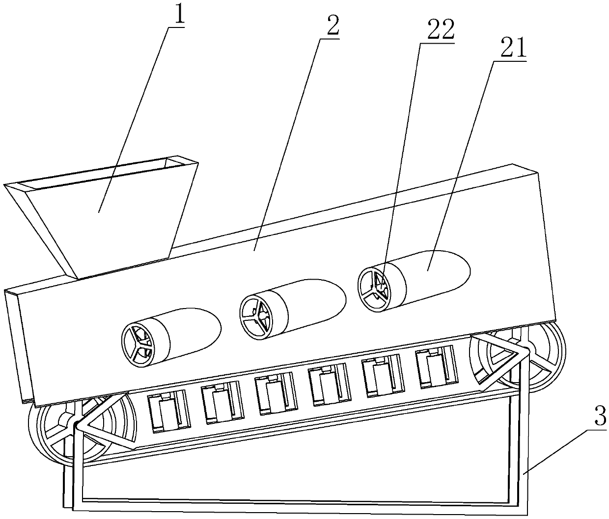
[0038] Embodiment one, see Figure 1-4 , this embodiment discloses a light material separation device, including an air supply mechanism and a material throwing mechanism, the air supply mechanism includes a sealing cover 2 buckled above the material throwing mechanism, and an air inlet arranged on the sealing cover 2 The duct 21 and the air inlet duct 21 are symmetrically welded on both sides of the sealing cover 2, and form an angle of 45 degrees with the sealing cover 2. The air inlet duct 21 is symmetrically arranged on both sides of the sealing cover 2. Blow the material from the side at the same time, so that the material is more evenly exposed to the wind. The air inlet pipe 21 is arranged obliquely on the sealing cover 2, so that the material not only receives an upward force but also a forward force when it is exposed to the wind, which is beneficial to the material. Sorting and transportation, improve sorting and conveying efficiency; The air inlet duct 21 is multipl...

Embodiment 2

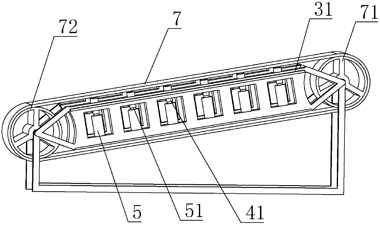
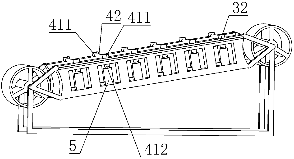
[0041] Embodiment two, see Figure 5-10 , this embodiment discloses a light material separation device, including an air supply mechanism and a material throwing mechanism, the air supply mechanism includes a sealing cover 2 buckled above the material throwing mechanism, and an air inlet arranged on the sealing cover 2 The duct 21 and the air inlet duct 21 are symmetrically welded on both sides of the sealing cover 2, and form an angle of 45 degrees with the sealing cover 2. The air inlet duct 21 is symmetrically arranged on both sides of the sealing cover 2. Blow the material from the side at the same time, so that the material is more evenly exposed to the wind. The air inlet pipe 21 is arranged obliquely on the sealing cover 2, so that the material not only receives an upward force but also a forward force when it is exposed to the wind, which is beneficial to the material. Sorting and transportation, improve sorting and conveying efficiency; In the present embodiment, the ...


PUM


Abstract

The invention provides a light material separation device. The device comprises a wind supply mechanism for blowing wind to a material and a material throwing mechanism for throwing the material up; and the wind supply mechanism comprises a sealing cover which is arranged above the material throwing mechanism in a covering mode and air inlet pipelines which are symmetrically arranged on two sidesof the sealing cover, and a wind force source provides wind force to the material through the air inlet pipelines. According to the device, by arranging the wind supply mechanism and the material throwing mechanism, the technical problem that the light material and the heavy material are mixed and extruded together and can not fully receive the wind, and thus the separation effect is poor is solved, and the separation effect of the light material is improved under the combined action of the material throwing and the wind blowing.

Description

technical field [0001] The invention belongs to the technical field of construction waste treatment, in particular to a light material separation device. Background technique [0002] With the acceleration of urbanization in our country, the process of urban renewal is accompanied by a large number of building demolition and demolition, resulting in a large amount of construction waste. If it is not handled properly, it will cause environmental pollution and waste of resources. The construction waste after building demolition and demolition is often mixed Decoration waste, construction waste is mostly heavy materials such as concrete blocks, crushed stones, bricks and tiles, and decoration waste is mostly light materials such as gypsum board, wallpaper, plastic, cloth art, etc. All kinds of waste are mixed together for waste disposal And reuse brings a lot of inconvenience. At present, manual sorting, water selection and winnowing are mostly used for sorting construction wa...

Claims


Application Information

Patent Timeline
IPC IPC(8): B07B7/01B07B11/06B07B11/02
CPCB07B4/025B07B11/00B07B11/06B07B4/02B07B7/01B07B9/00B07B11/02B09B3/00Y02W30/58
Inventor 朱兴良
Owner 义乌市铭耀智能科技有限公司
Why Eureka
Try Eureka