Method for realizing crack resistance of concrete beam member by optimizing ribbed FRP bars

A technology of concrete beams and ribs, which is applied in bridges, bridge construction, erection/assembly of bridges, etc., can solve the problems of small number of cracks, poor ductility, large crack width, etc., and achieve flexible construction methods, safe and convenient use, and scientific structure reasonable effect

Inactive Publication Date: 2020-05-19
江苏绿材谷新材料科技发展有限公司
View PDF5 Cites 1 Cited by
  • Summary
  • Abstract
  • Description
  • Claims
  • Application Information

AI Technical Summary

Problems solved by technology

[0002] At present, bridge structures are facing a major problem in harsh environments such as ocean, humidity, and saline-alkali land, that is, corrosion of steel bars. Corrosion of steel bars is the main reason for the deterioration of concrete components such as concrete box girders, concrete piers, and concrete piles in harsh environments. The reason is that fiber reinforced composites (FRP) have the advantages of light weight, high strength, corrosion resistance and fatigue resistance, and have received more and more attention in the field of civil engineering. At the same time, due to the low elastic modulus of FRP tendons, FRP Reinforced concrete beams show greater deformation, and the crack width is large, the crack spacing is relatively large, and the number of cracks is small. The failure mode of the beam in the bending state is brittle failure, there is no plastic deformation stage, the ductility is poor, the elongation is low, and there is no obvious deformation sign before failure, so there is an urgent need for a crack-resistant concrete beam member by optimizing the ribbed FRP reinforcement method to solve the above problems

Method used


Image

  • Method for realizing crack resistance of concrete beam member by optimizing ribbed FRP bars
  • Method for realizing crack resistance of concrete beam member by optimizing ribbed FRP bars
  • Method for realizing crack resistance of concrete beam member by optimizing ribbed FRP bars

Examples


Embodiment 1

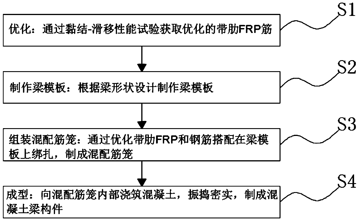
[0038] Example 1, such as figure 2 As shown, the cross-section of the mixed reinforcement cage in step S3 is a rectangular cross-section, including the lower longitudinal reinforcement 101 near the bottom of the beam, the stirrup 4 using optimized ribbed FRP reinforcement, the lower longitudinal reinforcement 102, the upper longitudinal reinforcement 2, and the waist near the bottom of the beam. Both the rib 3 and the middle tie bar 9 can be ordinary steel bars, the lower longitudinal bar 1 and the upper longitudinal bar 2 are bound on the inside of the stirrup 4, and the waist bar 3 is fixed on the inner middle of the stirrup 4 after being tied by the middle tie bar 9. After the mixed reinforcement cage is bound, put it into the pre-fabricated formwork, pour concrete 5, vibrate and compact it, and then maintain it. Among them, if the height of the beam section is less than 450mm, it is not necessary to set the waist reinforcement and the central tension reinforcement.

Embodiment 2

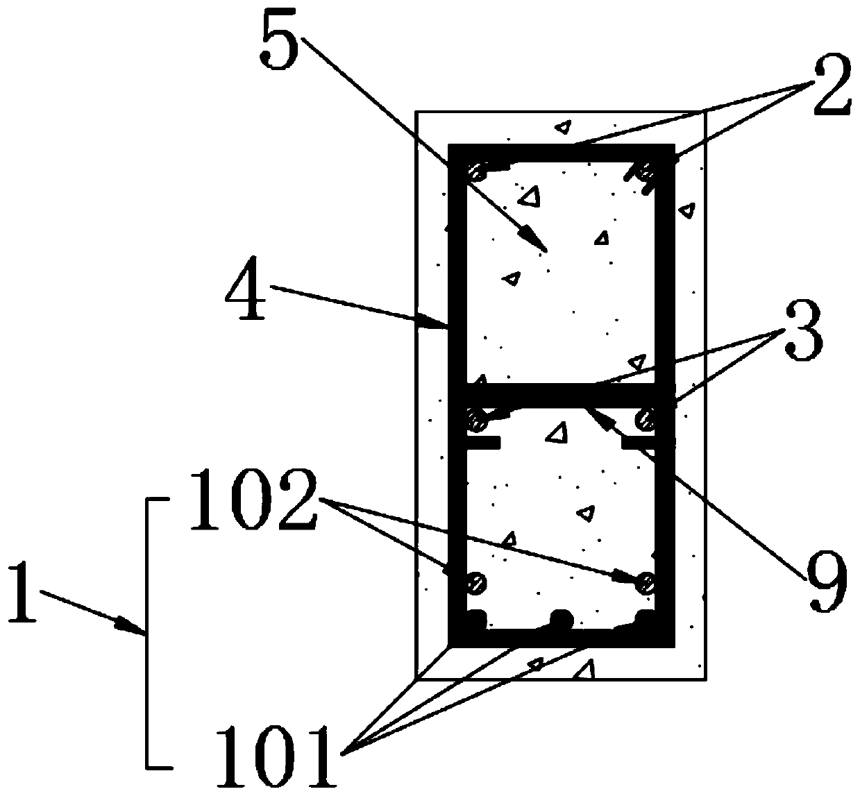
[0039] Example 2, such as image 3 As shown, the cross-section of the mixed reinforcement cage in step S3 is a T-shaped cross-section or an inverted T-shaped cross-section, and the reinforcement configuration of the web part of the two T-shaped cross-sections is consistent with the rectangular cross-section of Embodiment 1. The difference is that, as image 3 As shown in a, when binding the T-shaped cross-section mixed reinforcement cage, the reinforcement on the inner side of the upper longitudinal reinforcement 2 is first bound in the stirrup 4, and then the upper reinforcement 8 is used to tie the reinforcement on both sides of the upper longitudinal reinforcement 2 together. Binding with the inner steel bar of the upper longitudinal bar 2 and the stirrup bar 4, such as image 3 As shown in b, when binding the inverted T-shaped cross-section mixed reinforcement cage, the reinforcement inside the lower longitudinal reinforcement 1 is first bound in the stirrup 4, and then th...

Embodiment 3

[0040] Example 3, such as Figure 4As shown, the section of the mixed reinforcement cage in step S3 is an I-shaped cross section, and the configuration of the reinforcing bars of the I-shaped section web part is consistent with the rectangular section of Example 1. The difference is that when the I-shaped cross-section mixed reinforcement cage is bound, the I The steel bars on both sides of the lower longitudinal bar 1 of the I-shaped section are tied together and then bound with the inner steel bar of the lower longitudinal bar 1 and the stirrup 4, and the inner steel bar of the upper longitudinal bar 2 of the I-shaped section is bound in the stirrup 4 first, and then the upper tension bar is used The tendon 8 binds the steel bars on both sides of the upper longitudinal bar 2 together and then binds the inner steel bar of the upper longitudinal bar 2 and the stirrup 4 .


PUM


Abstract

The invention discloses a method for realizing crack resistance of a concrete beam member by optimizing ribbed FRP bars. The method comprises the steps of optimizing, manufacturing of a beam template,assembling of a mixed reinforcement cage and forming, the concrete beam member is reinforced by adopting the mixed reinforcement of the FRP bars and reinforcing bars, compared with single reinforcingbar reinforcement, the characteristics of high tensile strength and corrosion resistance of the FRP bars and good ductility of common reinforcing bars are sufficiently utilized, mutual complementation is realized, the defects of large deflection and crack width and insufficient ductility of the FRP reinforced concrete flexural member are overcome, the FRP bars are configured to the easy-to-corrode corner of the concrete beam member, the problem of steel bar corrosion of the reinforced concrete beam member and the defects of large deflection, wide cracks and brittle failure of the FRP reinforced concrete beam member are solved, the FRP bars are optimized, the problems that the bonding stress of the common ribbed FRP bars and concrete is small, bonding sliding performance is poor, the crackwidth cannot be effectively controlled are solved, and steel bars on the inner side are still likely to corrode are solved, the construction method is flexible, and both factory prefabrication and in-place casting can be realized.

Description

technical field [0001] The invention relates to the technical field of civil structural engineering, in particular to a method for realizing crack resistance of concrete beam members by optimizing ribbed FRP bars. Background technique [0002] At present, bridge structures are facing a major problem in harsh environments such as ocean, humidity, and saline-alkali land, that is, corrosion of steel bars. Corrosion of steel bars is the main reason for the deterioration of concrete components such as concrete box girders, concrete piers, and concrete piles in harsh environments. The reason is that fiber reinforced composites (FRP) have the advantages of light weight, high strength, corrosion resistance and fatigue resistance, and have received more and more attention in the field of civil engineering. At the same time, due to the low elastic modulus of FRP tendons, FRP Reinforced concrete beams show greater deformation, and the crack width is large, the crack spacing is relative...

Claims


Application Information

Patent Timeline
Patent Type & Authority Applications(China)
IPC IPC(8): B28B1/04B28B1/52B28B23/02E01D21/00
CPCB28B1/045B28B1/52B28B23/02E01D21/00
Inventor 汪昕吴智深史健喆刘长源朱中国钱璐
Owner 江苏绿材谷新材料科技发展有限公司
Why Eureka
Try Eureka