Brake-by-wire device with redundancy function and control method thereof

A brake-by-wire, functional technology, applied in the direction of brake transmission, brake, brake components, etc., can solve the problems of low modularity, high cost, no integrated design, etc., and achieve the effect of reducing cost

Active Publication Date: 2020-05-19
SHANDONG JIAOTONG UNIV
View PDF6 Cites 0 Cited by
  • Summary
  • Abstract
  • Description
  • Claims
  • Application Information

AI Technical Summary

Problems solved by technology

[0005] Although the existing electronic hydraulic brake system (EHB) uses an electronic brake pedal, its brake pressure is provided by a plunger pump driven by a motor, and a high-pressure accumulator is used to store pressure, and the backup brake system More isolation solenoid valves are used in the system, so that the whole system has more parts and higher cost
In addition, in the existing braking system, the master cylinder and the pressure regulating unit are not integrated, the degree of modularization is not high, the length of the brake pipeline is increased, and the brake pressure response is slow
Since the brake pipeline will undergo elastic deformation under the action of high-pressure brake fluid, the pressure of the brake fluid in the brake pipeline will fluctuate, which will greatly affect the precise control of vehicle braking.

Method used


Image

  • Brake-by-wire device with redundancy function and control method thereof
  • Brake-by-wire device with redundancy function and control method thereof
  • Brake-by-wire device with redundancy function and control method thereof

Examples


Embodiment Construction

[0037] In order to clearly illustrate the technical features of the solution, the solution will be described below through a specific implementation mode and in conjunction with the accompanying drawings.

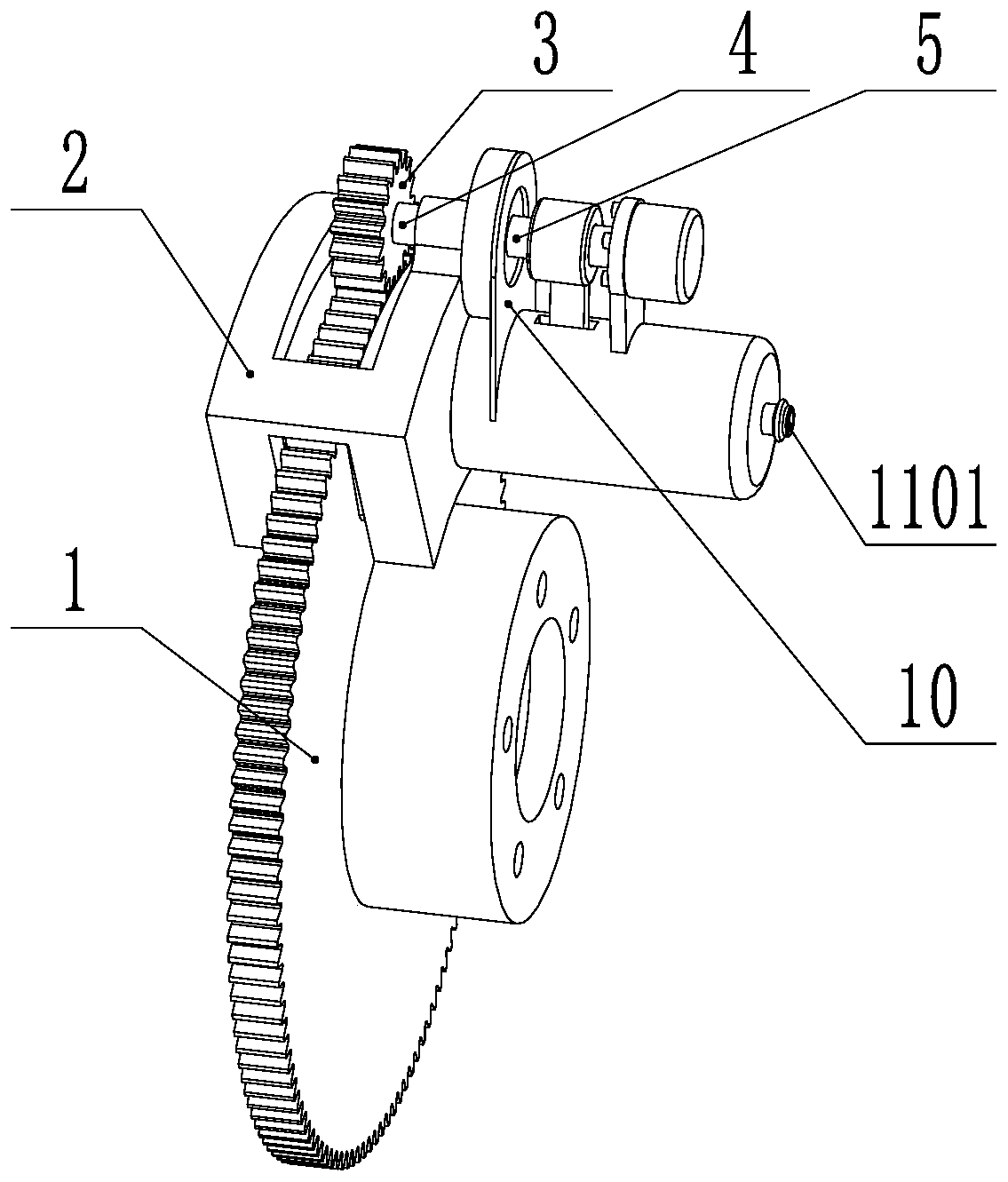
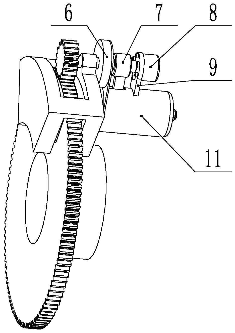
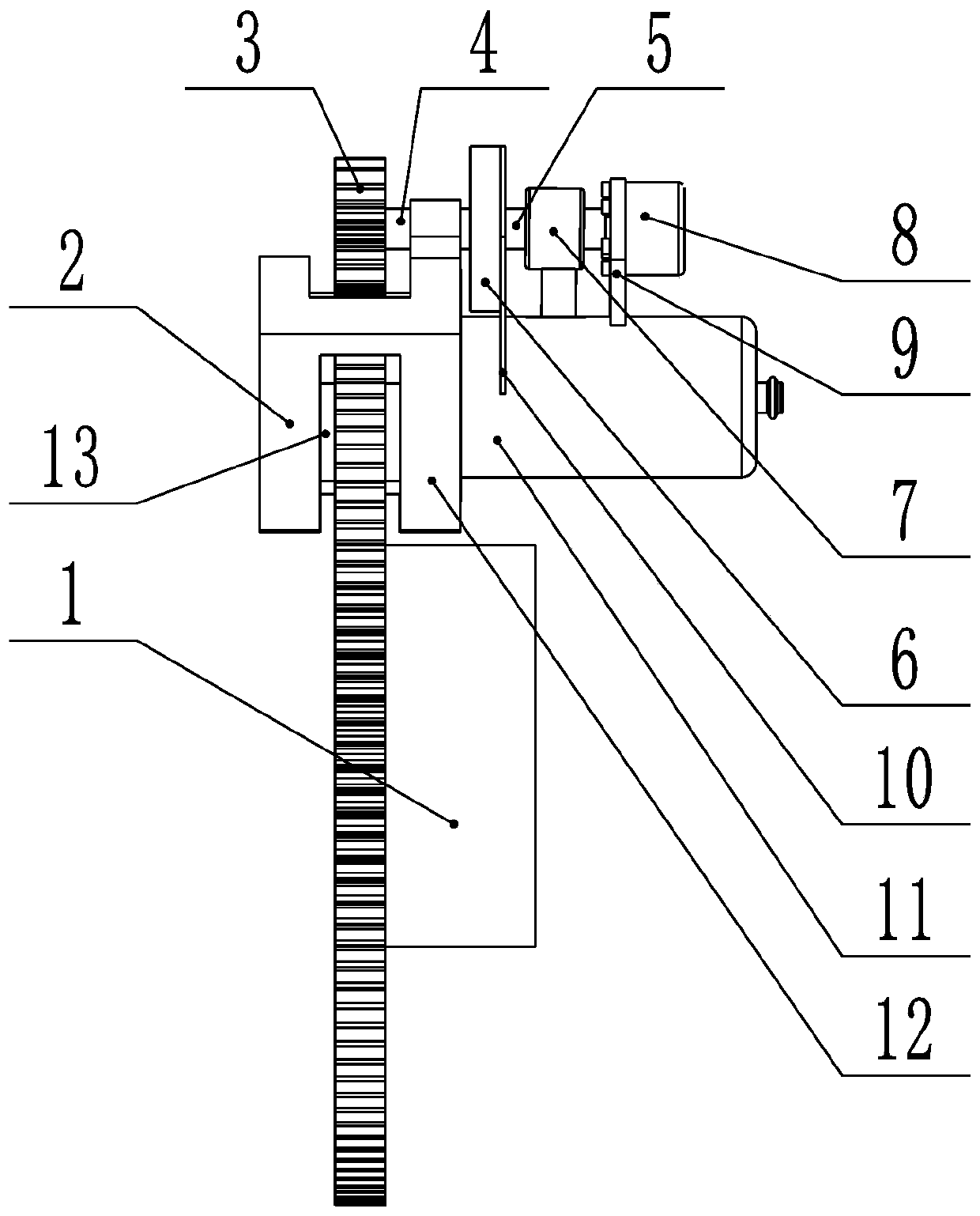
[0038] A brake-by-wire device with redundant functions, including a brake disc 1, a caliper 2, a power take-off gear 3, a gear shaft 4, a screw shaft 5, an electromagnetic clutch 6, a nut assembly 7, a return motor 8, and a motor bracket 9. Bracket 10, brake cylinder 11, right friction plate 12, left friction plate 13, brake piston 14, oil storage tank 15, brake master cylinder 16, brake piston push rod assembly 17, brake pedal 18, angle sensor 19. The first two-position two-way solenoid valve 20, the second two-position two-way solenoid valve 21, the vehicle speed sensor 22, the controller 23, and the gear position sensor 24;

[0039] Such as figure 1 , figure 2 , image 3 As shown, the brake disc 1 is fixedly installed on the axle, and the left friction plate 13 and t...


PUM


Abstract

The invention relates to a brake-by-wire device with a redundancy function and a control method thereof. The device comprises a brake disc, calipers, a power take-off gear, a gear shaft, a lead screwshaft, an electromagnetic clutch, a nut assembly, a return motor, a motor support, a support, a brake oil cylinder, a right friction plate, a left friction plate, a first two-position two-way electromagnetic valve, a second two-position two-way electromagnetic valve, a vehicle speed sensor, a controller and a gear sensor. Vehicle kinetic energy can be fully utilized as a power source, a driving motor adopted in the prior art is omitted, and the cost is effectively reduced; a gear power take-off mechanism is used for driving an execution structure to generate braking force, and the braking force of a brake is controlled through the electromagnetic clutch. A redundancy function is realized through coupling with a conventional hydraulic braking system; the brake-by-wire device has the advantages of the high integration level, the high response speed and low cost; and when a vehicle is braked and locked, a hydraulic braking switch control mode is changed into a braking force continuous adjustable mode, and higher control precision is achieved.

Description

technical field [0001] The invention relates to the field of automobile brakes, in particular to a brake-by-wire device with redundant functions and a control method. Background technique [0002] Brake-by-wire technology is a new type of braking technology that has emerged in recent years. It does not rely on mechanical or hydraulic connections between the brake and the brake pedal. It uses wires to replace part or all of the brake pipelines, and controls the electronic control through the controller. The components are used to control the braking force and realize the stable and reliable braking control of the car. At present, the brake-by-wire system mainly includes two types: electro-hydraulic brake system (EHB) and electro-mechanical brake system (EMB). The brake-by-wire system is conducive to the optimization of the braking performance of the whole vehicle, and can be easily integrated with other electronic control systems such as ABS, ASR, ESP, etc., so it has a broa...

Claims


Application Information

Patent Timeline
Patent Type & Authority Applications(China)
IPC IPC(8): B60T13/58B60T13/68
CPCB60T13/588B60T13/686B60T2270/402B60T2270/82
Inventor 张竹林王健许本博蒋德飞戴汝泉王金波
Owner SHANDONG JIAOTONG UNIV
Why Eureka
Try Eureka