Precast beam precise lifting device and method thereof

A lifting device and prefabricated beam technology, applied in the direction of transportation and packaging, load hanging components, etc., can solve the problems of reserved holes, high hoisting costs, dense steel bars, etc., to ensure safety and reliability, use and Simple and convenient operation, simple and precise hoisting effect

Pending Publication Date: 2020-05-19
GUANGDONG PROVINCIAL ARCHITECTURAL ENG MACHINERY CONSTR
View PDF1 Cites 4 Cited by
  • Summary
  • Abstract
  • Description
  • Claims
  • Application Information

AI Technical Summary

Problems solved by technology

When the prefabricated beam is hoisted by this method, the following problems are likely to occur: 1. The beam body generally has a small cross-section and dense steel bars. In addition to the layout of the prestressed tunnel and the error during construction, it is difficult to implement the pre-embedded large-diameter round steel ring. ; 2. The weight of the beam body is relatively large, and the round steel rings are subjected to concentrated and large forces. If the rings are slightly damaged during processing, the rings are easily damaged during the lifting process, resulting in safety accidents; 3. The embedded round steel rings are only As a lifting tool, it has no effect on the beam structure. It cannot be reused when it is embedded in the beam concrete structure during beam construction. If the prefabricated amount is large, the round steel will be wasted and the cost will be high
[0004] At the same time, there are many defects in the lifting prefabricated beam spreader of the bridge prefabricated factory. For example, in the patent CN201420153775.8 (lifting prefabricated beam spreader for the bridge prefabricated factory), two devices similar to electric hoists are required to be connected simultaneously at both ends during hoisting. Vertical hoisting is too wasteful of resources and the hoisting cost is high, and the spreader needs to destroy the prefabricated beam itself during hoisting, such as reserving holes on the prefabricated beam, so that the reserved hole will be left crooked during operation, causing secondary damage to the prefabricated beam itself and the problem of reducing the bearing capacity of prefabricated beams
At the same time, since this kind of spreader needs to be lifted at both ends at the same time, if one of the lifting devices is broken, it cannot be hoisted, and the practicability and mobility are poor.

Method used


Image

  • Precast beam precise lifting device and method thereof
  • Precast beam precise lifting device and method thereof
  • Precast beam precise lifting device and method thereof

Examples


Embodiment 1

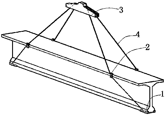
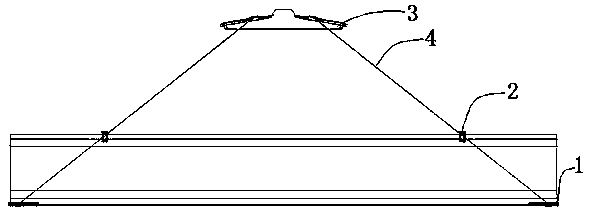
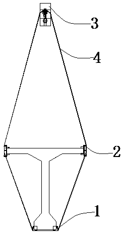
[0046] This embodiment provides a prefabricated beam precise lifting device, such as Figure 1-7 As shown, the device is used for hoisting prefabricated beams, including supporting parts 1, buffer plates 2, pole beams 3 and steel wire ropes 4; during hoisting, supporting parts 1 are arranged at the corners of the bottom of prefabricated beams, and buffer plates 2 is set on the flange of the prefabricated beam, while the shoulder beam 3 is located at the lifting point, and the steel wire rope 4 is wound and tightened on the supporting member 1, the buffer plate 2 and the shoulder beam 3, thereby hoisting the prefabricated beam.

[0047] The advantage is that the device is simple to manufacture, can be recycled, and is suitable for different beam lengths. At the same time, the hoisting is simple and precise. The construction personnel can complete the precise hoisting only through simple operations, completely solving the problem of "top-heavy" when hoisting beams. Phenomenon. ...

Embodiment 2

[0060] This embodiment is similar to the first embodiment, the difference lies in the structure of the support plate 13 and the position adjustment device 5 of the shoulder beam 3 .

[0061] Specifically, such as Figure 1-7 As shown, the positioning device 5 also includes an elastic member 53, the elastic member 53 includes a fixed end and a movable end, the elastic member 53 is connected with the other end of the first slider 11 or the second slider 31 through the movable end, and its main The function is to buffer or drive the sliding of the first slider 11 or the second slider 31 on the chute. In this embodiment, the elastic member 53 is a spring.

[0062] More specifically, for a better user experience, the specific structure of the positioning device 5 in this embodiment is provided. Specifically, the elastic member 53 in the positioning device 5 is a spring, and the positioning assembly 51 includes bolts, nuts and threaded boxes. In terms of the supporting member 1, ...

Embodiment 3

[0066] Such as Figure 8 As shown, this embodiment provides a method for precise lifting of prefabricated beams, which is applied to precise lifting devices for prefabricated beams, including:

[0067] S1. Installation of supporting member 1: Install supporting member 1 at the four end corners of the beam rib of the prefabricated beam, and attach the limiting plate 12 and the supporting plate 13 to the beam rib;

[0068] S2. Position adjustment of the first slider 11: Pass the two steel wire ropes 4 under the two ends of the beam rib of the prefabricated beam respectively, and lock them in the slot 6 of the first slider 11 of the two supporting parts 1 at the same end of the beam rib Firstly, adjust the position of the first slider 11 on the supporting member 1 according to the length of the prefabricated beam and use the adjustment ruler, and then position the first slider 11 through the positioning assembly 51;

[0069] S3. Installation of the buffer plate 2: Determine the ...


PUM


Abstract

The invention relates to the technical field of bridge precast structure lifting, in particular to a precast beam precise lifting device and a method thereof. The precast beam precise lifting device is used for lifting a precast beam and comprises supporting pieces, buffering plates, a carrying pole beam and steel wire ropes; during lifting, the supporting pieces are arranged at corners of the bottom of the precast beam so that the precast beam can be limited and supported; the buffering plates are arranged on flanges of the precast beam and used for positioning the steel wire ropes and buffering the acting force of the steel wire ropes to the precast beam; the carrying pole beam is located at the lifting point; and the lifting device completes precise lifting of the precast beam by winding the steel wire ropes around a first slide block, a second slide block and clamping grooves of the buffering plates. The lifting device is easy to manufacture, capable of achieving cyclic utilization, and suitable for different beam lengths, meanwhile, lifting is easy and precise, constructors can complete precise lifting only through easy operation, the top-heavy phenomenon during beam lifting is completely avoided, in addition, application is wide, the carrying pole beam does not need to be replaced during lifting, the lifting cost is greatly reduced, and the precast beam lifting efficiencyis improved.

Description

technical field [0001] The invention relates to the technical field of bridge prefabricated construction hoisting, in particular to a prefabricated beam precise hoisting device and method thereof. Background technique [0002] During the prefabrication construction process of various bridge girder structures (such as T beam, 1 beam, U beam, small box girder, etc.), due to the heavy weight of the beam body, the beam needs to be moved to a suitable position after the prefabrication of the concrete beam is completed, forming Only assembly line operation can reduce costs without affecting the overall construction schedule. How to ensure the safety of concrete beams and construction personnel during the beam-moving operation is a problem that must be solved. Especially in the process of bridging rack girder operation, the safety in the construction process must be guaranteed. [0003] At present, in the hoisting construction of prefabricated beams, the usual solution is to pre-...

Claims


Application Information

Patent Timeline
Patent Type & Authority Applications(China)
IPC IPC(8): B66C1/12
CPCB66C1/12B66C1/122
Inventor 纪孟辉苏勇维廖伟东姚色丰郑康洲高媚陈继壮
Owner GUANGDONG PROVINCIAL ARCHITECTURAL ENG MACHINERY CONSTR
Why Eureka
Try Eureka