Microbubble molten steel purification device and purification method

A purification device and micro-bubble technology, applied in the field of iron and steel smelting, can solve the problems of limited degree of micro-bubble, limited purification effect, and difficulty in avoiding large bubbles, etc., and achieve the effect of increasing the rotational speed, reducing the rotational resistance and improving the purification effect.

Active Publication Date: 2020-05-19
ANGANG STEEL CO LTD
View PDF10 Cites 1 Cited by
  • Summary
  • Abstract
  • Description
  • Claims
  • Application Information

AI Technical Summary

Problems solved by technology

For example, direct use of special air-permeable elements to form micro-bubbles to purify molten steel, but practical applications show that the degree of micro-bubbles directly formed through breathable bricks is limited, and it is difficult to avoid the generation of large bubbles, so the purification effect is limited
[0006] CN103074468A Although contained CaCO 3 Pyrolysis can release small bubbles, but this method is added to the steel in the form of a solvent, and it is difficult for the decomposed bubbles to enter the molten steel, so the best removal effect of inclusions cannot be achieved

Method used


Image

  • Microbubble molten steel purification device and purification method
  • Microbubble molten steel purification device and purification method

Examples


Embodiment 1

[0031] The test steel is pipeline steel

[0032] (1) Transport the ladle containing the molten steel to be treated to the microbubble purification station.

[0033] (2) Argon gas is blown at the bottom of the ladle, and the flow rate is controlled at 200L / min, and there is no steel slag in the middle area of ​​the ladle.

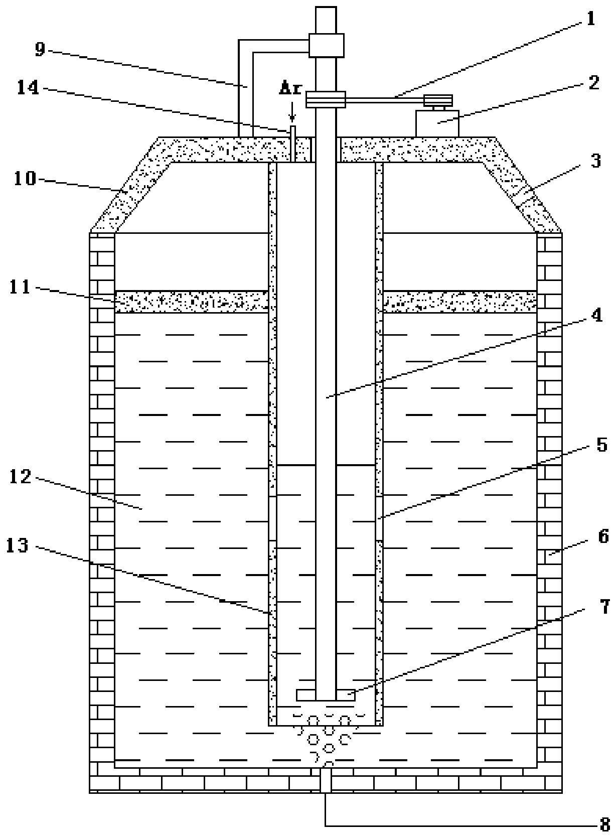
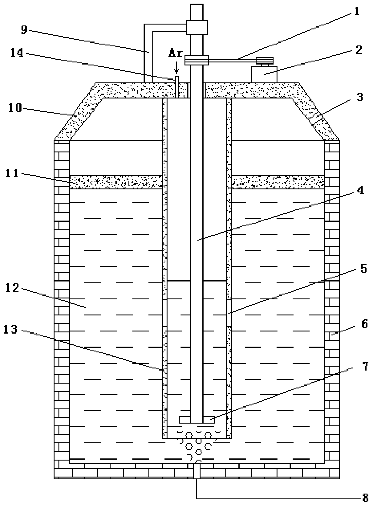
[0034] (3) Lower the rotating shaft, the stirring paddle and the protective cylinder to the inside of the molten steel until the top cover 10 is in contact with the upper edge of the ladle.

[0035] (4) Blow in argon gas from the argon gas inlet pipe to press the liquid steel surface in the protective cylinder to a low place, and the liquid level is 120mm away from the upper edge of the tapping hole on the protective cylinder.

[0036] (5) Control the flow rate of low-blown argon gas in the ladle at 30 L / min, start the motor to drive the rotating shaft to rotate, and control the speed at 300 rpm; the processing time is 8 minutes.

[0037] (6) After the tre...

Embodiment 2

[0040] The test steel is IF steel

[0041] (1) Transport the ladle containing the molten steel to be treated to the microbubble purification station.

[0042] (2) Argon gas is blown at the bottom of the ladle, and the flow rate is controlled at 300L / min, and there is no steel slag in the middle area of ​​the ladle.

[0043] (3) Lower the rotating shaft, the stirring paddle and the protective cylinder to the inside of the molten steel until the top cover 10 is in contact with the upper edge of the ladle.

[0044] (4) Blow in argon gas from the argon gas inlet pipe to press the liquid steel surface in the protective cylinder to a low place, and the liquid level is 150mm away from the upper edge of the tapping hole on the protective cylinder.

[0045] (5) Control the flow rate of low-blown argon gas in the ladle at 80 L / min, start the motor to drive the rotating shaft to rotate, and control the rotating speed at 800 rpm; the processing time is 5 minutes.

[0046] (6) After the ...


PUM


Abstract

The invention discloses a microbubble molten steel purification device and purification method. The purification device comprises a steel ladle, wherein air bricks are arranged at the bottom of the steel ladle, and a top cover is arranged at the top of the steel ladle; the top cover is fixedly connected with one end of a supporting frame, and the other end of the supporting frame is connected witha rotating rod through a rotating shaft; the rotating rod penetrates through the top cover to enter into the steel ladle, the bottom of the rotating rod is connected with a stirring paddle, and the rotating rod is driven by a driving device; a protective barrel is arranged on the periphery of the rotating rod, the protective barrel is fixed at the bottom of the top cover, and the protective barrel is provided with tapping holes; and the top cover is provided with an air inlet pipe and an exhaust hole, and the air inlet pipe is arranged in an area between the rotating rod of the top cover andthe protective barrel. Bottom blowing bubbles are crushed into a large number of microbubbles through stirring blades rotating at high speed, it can be guaranteed that a large number of dispersed microbubbles are formed in molten steel through molten steel circulation, and the purpose of molten steel purification is achieved through the microbubbles.

Description

technical field [0001] The invention belongs to the field of iron and steel smelting, and in particular relates to a technology for purifying molten steel by using microbubbles. Background technique [0002] The production of pure steel has always been the goal pursued by metallurgists. However, in the process of steel production, impurities and non-metallic inclusions will inevitably enter molten steel. Before continuous casting, if these non-metallic inclusions If it cannot be effectively removed, the non-metallic inclusions will remain in the slab, which will eventually cause great harm to the mechanical and physical properties of the steel. Taking stainless steel as an example, in the rolling process, the existence of inclusions not only affects the surface finish of stainless steel sheets, but also reduces the anti-corrosion ability of products. At present, the scrap rate of products caused by inclusions in domestic stainless steel factories is as high as 20% or even hi...

Claims


Application Information

Patent Timeline
IPC IPC(8): C21C7/072
CPCC21C7/0075C21C7/072
Inventor 廖相巍尚德礼张晓光赵亮万雪峰张维维曹东李广帮李德军
Owner ANGANG STEEL CO LTD
Why Eureka
Try Eureka