Diversion grid structure and construction method suitable for downstream bends of approach channel

A technology of diversion grate and approach channel, which is applied in the field of ship lock approach channel, can solve problems such as unsolvable engineering problems, shoals in river channels, navigation safety accidents, etc., and achieves good promotion and application prospects, and reduces construction difficulty and construction cost.

Active Publication Date: 2022-03-15
TIANJIN RES INST FOR WATER TRANSPORT ENG M O T
View PDF9 Cites 0 Cited by
  • Summary
  • Abstract
  • Description
  • Claims
  • Application Information

AI Technical Summary

Problems solved by technology

[0004] However, when there is a sharp bend in the river not far from the downstream of the building and shoals appear in the channel outside the approach channel, the middle elevation of the channel is higher than the approach channel, and a large amount of sediment is deposited at the bottom of the channel, the traditional method will not be able to solve this engineering problem
If the traditional guide wall is built, the downstream channel of the building will be backed up significantly, endangering the safety of buildings on both sides of the river; if the guide wall is not built, due to the erosion of the water flow, the sediment in the shoal will be brought into the approach channel, thereby blocking the approach channel, and even worse Seriously, the oblique flow formed by the sharp bends and shoals of the river will cause the ship to yaw, causing serious navigation safety accidents

Method used


Image

  • Diversion grid structure and construction method suitable for downstream bends of approach channel
  • Diversion grid structure and construction method suitable for downstream bends of approach channel
  • Diversion grid structure and construction method suitable for downstream bends of approach channel

Examples


Embodiment Construction

[0025] The technical solution of the present invention will be further described below in conjunction with the accompanying drawings.

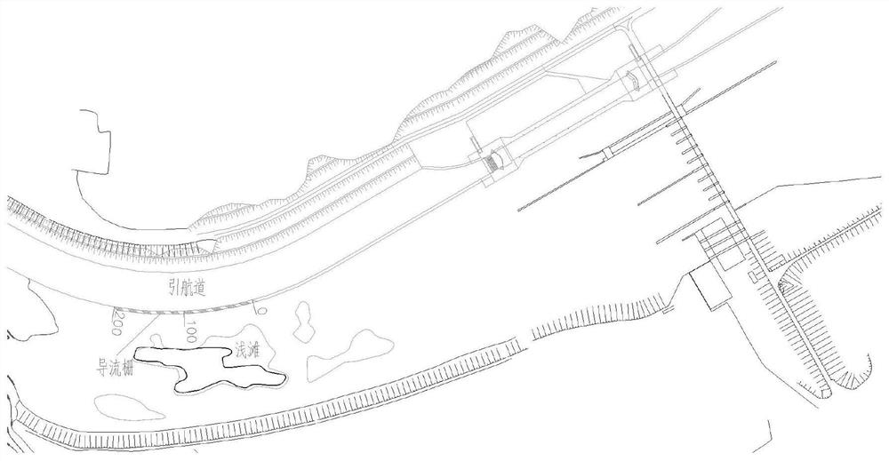
[0026] In this case, there is a sharp bend 400 meters downstream of the ship lock, and there is a shoal in the channel outside the approach channel at the bend, and the elevation of the river channel is significantly higher than the elevation inside the approach channel. , it is necessary to build a guide wall at this position; considering that there is a sharp bend at this position, if a traditional guide wall is built, it will inevitably cause abnormally high water levels upstream of the bend. Therefore, the diversion grid structure of the present invention is arranged at this position, and the length of the diversion grid arrangement is 200 meters, which basically covers the sharp bend river course. For details, see figure 1 .

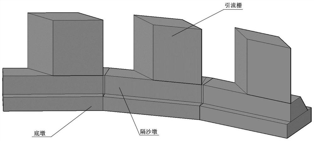
[0027] The diversion fence structure formed by connecting multiple diversion fence units is as follows: image ...


PUM


Abstract

The invention relates to a diversion fence structure suitable for a bend in the downstream of an approach channel and a construction method thereof. The diversion fence structure is formed by connecting a plurality of diversion fence units; the one diversion fence unit sequentially includes from top to bottom The bottom pier, the sand pier and the drainage grid; the bottom pier is a cuboid structure; the sand pier is arranged on the bottom pier, the longitudinal section of the sand pier is a right-angled trapezoid, the side near the approach channel is a right angle, and the side near the river is a slope ; The drainage grid is arranged on the sand pier. The diversion grid structure of the present invention is suitable for the terrain where the approach channel downstream of the ship lock has a sharp bend and there is a shoal outside the approach channel, the elevation is significantly higher than the approach channel, and the excavation volume of the shoal is too large or it is inconvenient to excavate. The diversion grid structure can effectively solve this problem. Engineering problems caused by special terrain. The role of the diversion grid is to avoid the hazards of oblique flow and sediment transportation, ensure the normal navigation of the ship lock approach channel, ensure the normal upstream water level and flow state, reduce construction difficulty and construction cost, and have a good prospect for promotion and application.

Description

technical field [0001] The invention belongs to the field of ship lock approach channels, and in particular relates to a diversion grid structure and a construction method thereof for improving the navigation conditions downstream of the ship lock approach channel and the water flow conditions of the downstream channel of the ship lock. Background technique [0002] With the continuous improvement and improvement of people's living standards, the demand for energy has further increased, the volume of passenger and cargo transportation has increased rapidly year by year, and the constraints on resources and the environment have become increasingly severe. At present, my country's national conditions determine that the development of energy and transportation cannot be slowed down. Therefore, the contradiction between the development of transportation and the reduction of energy consumption and environmental pollution is becoming increasingly acute, which will inevitably lead t...

Claims


Application Information

Patent Timeline
Patent Type & Authority Patents(China)
IPC IPC(8): E02B3/00E02C1/00
CPCE02B3/00E02C1/00Y02A10/30
Inventor 普晓刚闫涛冯小香乾东岳郝媛媛李少希王斐胡森涛林庆奇张俊豫许松覃益官赵凌宇王能张爱平邝晓路
Owner TIANJIN RES INST FOR WATER TRANSPORT ENG M O T
Why Eureka
Try Eureka