
Auxiliary transformer cabinet draught fan

A technology for auxiliary transformers and fans, which is applied in the direction of machines/engines, electromechanical devices, mechanical equipment, etc. It can solve the problems of internal flow field disorder of auxiliary transformer cabinet fans, deviation from rated operating point, and inability to be lifted, etc., to achieve a simplified structure, Unobstructed air flow and improved efficiency

Pending Publication Date: 2020-05-19
HUNAN LIANCHENG TRACK EQUIP CO LTD
View PDF0 Cites 0 Cited by
  • Summary
  • Abstract
  • Description
  • Claims
  • Application Information

AI Technical Summary

Problems solved by technology

[0004] The existing auxiliary transformer cabinet fan is a centrifugal fan structure with a volute side plate and a single outlet. In the prior art, due to the limitation of the shape and structure of the fan, the internal flow field of the auxiliary transformer cabinet fan is relatively disordered, and the efficiency of the fan has been at a relatively high level. The low level cannot be improved, and the high-efficiency point of the fan is located at the operating point of small flow, which is seriously deviated from the rated operating point, and the turbulent flow field will also bring large aerodynamic noise

Method used


Image

  • Auxiliary transformer cabinet draught fan
  • Auxiliary transformer cabinet draught fan
  • Auxiliary transformer cabinet draught fan

Examples


Embodiment

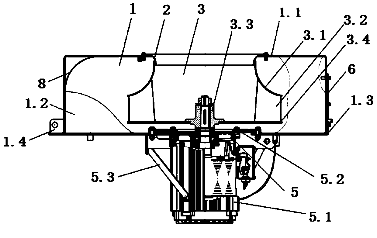
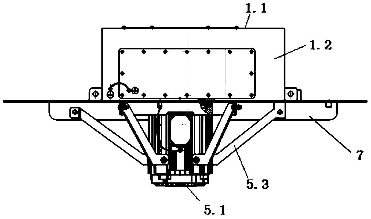
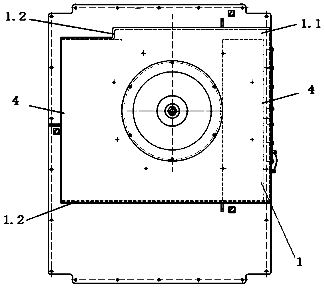
[0035] An auxiliary transformer cabinet fan, see Figure 1-3 , including casing assembly 1, air inlet 2, impeller 3, air outlet 4 and power source 5, the detailed structure is as follows:

[0036] The casing assembly 1 is a box-shaped casing structure formed by a casing cover plate 1.1, a casing side plate 1.2, and a casing bottom plate 1.3, and also includes lifting lugs 1.4, grounding blocks and other components. The box-shaped structure of the volute. The casing cover 1.1 is provided with an installation opening for installing the air inlet 2, the installation opening is opened in the middle of the casing cover 1.1, and the installation opening is a circular opening, and the periphery of the circular opening is A plurality of rivet nuts are uniformly arranged for fixing the air inlet 2 . The casing bottom plate 1.3 is provided with at least two air outlets 4, preferably two air outlets 4 with different specifications located at the left and right ends of the casing bottom...


PUM

PropertyMeasurementUnit
Arc radiusaaaaaaaaaa
Exit widthaaaaaaaaaa

Abstract

The invention provides an auxiliary transformer cabinet draught fan comprising a machine shell assembly, an air inlet, an impeller, an air outlet and a power source. The machine shell assembly is of abox-shaped shell structure formed by a machine shell cover plate, machine shell side plates and a machine shell bottom plate. An installation opening used for installing the air inlet is formed in the machine shell cove plate. At least two air outlets are formed in the machine shell bottom plate. The windward side of the air inlet is an arc-shaped face. The impeller is arranged in the box-shapedshell structure and is of a backward centrifugal type impeller structure. The impeller comprises a front wheel disc and blades. The surface of the end, close to the air inlet, of the front wheel discis an arc-shaped face. The blades are arc-shaped blades. When the draught fan is applied, the effect that the structure is simplified is achieved. By means of the unique design of the four parts, namely, the machine shell assembly, the air outlet, the air inlet and the impeller, the internal flow field of the draught fan can be well optimized, gas flow can be smoother, the overall work efficiencyof the auxiliary transformer cabinet draught fan can be better improved, generation of eddy noise can be well reduced, and the aims of energy conservation and noise reduction are achieved.

Description

technical field [0001] The invention relates to the technical field of fluid machinery, in particular to an auxiliary transformer cabinet fan. Background technique [0002] Auxiliary transformer cabinet cooling fan (auxiliary transformer cabinet fan) is an important component of the auxiliary transformer cabinet cooling system of electric locomotives. The auxiliary transformer cabinet cooling fan is installed vertically on the top of the auxiliary transformer cabinet. In order to achieve a good cooling effect of the auxiliary transformer of the electric locomotive, the cooling fan is required to provide as much air volume as possible. Due to the limitations of the space and layout of the auxiliary transformer cabinet in the locomotive, the structure of the cooling fan is limited, requiring a smaller fan size. [0003] As locomotives are heavily loaded and speeded up, and used in special environmental conditions, power components generate more heat and require higher ventil...

Claims


Application Information

Patent Timeline
IPC IPC(8): F04D25/08F04D17/16F04D29/42F04D29/28F04D29/30F04D29/44F04D29/66F04D29/02H02K7/14H02K5/24
CPCF04D17/16F04D25/0606F04D25/08F04D29/023F04D29/281F04D29/30F04D29/4213F04D29/4226F04D29/4246F04D29/441F04D29/661F04D29/666F05D2300/173H02K5/24H02K7/14
Inventor 张加贝屈小章翟方志
Owner HUNAN LIANCHENG TRACK EQUIP CO LTD
Learn More