Ice melting method and device for power transmission wire

A technology of power transmission wires and ice-melting methods, which is applied in the installation of cables, electrical components, overhead installations, etc., can solve the problems of difficult to deal with large-scale ice and snow disasters, poor deicing effect, and low work efficiency, and achieve a solution The problem of icing hazards, it is beneficial to popularization and application, and the effect of less electrical equipment

Inactive Publication Date: 2020-05-19
甘永忠
View PDF0 Cites 0 Cited by
  • Summary
  • Abstract
  • Description
  • Claims
  • Application Information

AI Technical Summary

Problems solved by technology

[0002] In cold weather, the power transmission line will be damaged by freezing itself or the surrounding environment and cause accidents. Due to the low probability of accidents and the high cost of existing technologies, general power transmission lines do not promote the use of ice-melting devices.
In the prior art, many solutions are electromechanical devices for deicing power transmission wires. Such devices have the problems of low working efficiency, difficult operation, and poor deicing effect, and it is difficult to deal with large-scale ice and snow disasters.
Another kind of DC ice melting technology is to input a large DC current into the transmission wire, and use the resistance of the wire to generate heat to melt the ice. This technology requires an external large-capacity DC power supply, and it needs to be carried out when the normal power supply of the line is interrupted. , the operation is complex
Lu Jiazheng and others invented a transmission line conductor suitable for live online melting of ice and its use method. When manufacturing the transmission conductor, a heating conductor is added along the conductor, and when necessary, the heating conductor is connected with an external working power supply for heating. The technology requires the use of special wires, which cannot be realized on existing lines

Method used


Image

  • Ice melting method and device for power transmission wire
  • Ice melting method and device for power transmission wire
  • Ice melting method and device for power transmission wire

Examples


Embodiment Construction

[0021] The present invention will be further described below through specific embodiments and in conjunction with the accompanying drawings. Apparently, the described embodiments are only some of the embodiments of the present invention, not all of them. Based on the embodiments of the present invention, all other implementations obtained by persons of ordinary skill in the art without making creative efforts fall within the protection scope of the present invention.

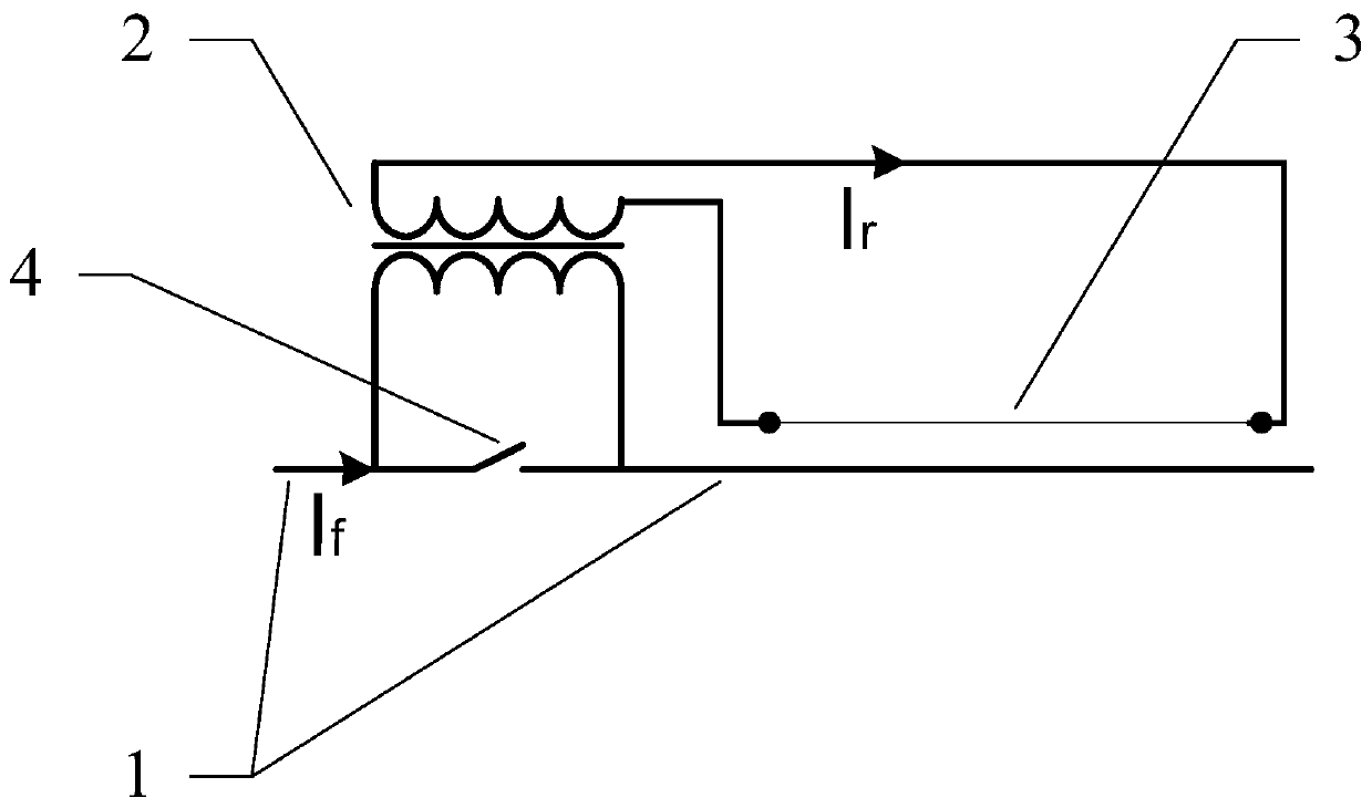
[0022] Such as figure 1 As shown, a method and device for melting ice for power transmission wires, comprising: power transmission wire 1, transformer 2, heating wire 3, switch A 4, the primary side coil of transformer 2 is connected in series with power transmission wire 1, and the secondary coil of transformer 2 The side coil is connected to the heating wire 3, which is arranged in parallel along the power transmission wire 1. The heating wire 3 has a certain resistance, and can pass a relatively large curren...


PUM


Abstract

The invention discloses an ice melting method and device for a power transmission wire and belongs to the technical field of electrical engineering, and the method and the device can effectively solvea problem of icing of the power transmission wire in actual operation. The method and the device are simple and reliable in working principle, low in manufacturing and using cost and flexible in installation and operation. The technical scheme is characterized in that a transformer is additionally arranged on the power transmission wire, a primary side coil of the transformer is connected into the power transmission wire in series, a secondary side coil of the transformer is connected into a heating wire, the transformer works in a current conversion state, a heating wire has a certain resistance and can generate heat when current passes through the heating wire, the heating wire is arranged in parallel along the power transmission wire, and switching equipment is installed at a connecting position of the power transmission wire and the transformer. The working principle is that an induced current is generated in a loop formed by the secondary side coil of the transformer and the heating wire by utilizing a load current of the power transmission wire, the induced current generates heat through the heating wire, and the power transmission wire and a nearby environment are heated and deiced by utilizing the heat.

Description

technical field [0001] The invention belongs to the technical field of electrical engineering, and relates to an ice-melting method and device for power transmission wires. Background technique [0002] In cold weather, power transmission wires may be damaged by freezing of themselves or the surrounding environment and cause accidents. Due to the low probability of accidents and the high cost of existing technologies, general power transmission wires have not promoted the use of ice-melting devices. In the prior art, many solutions are electromechanical devices for deicing power transmission wires. Such devices have the problems of low work efficiency, difficult operation, and poor deicing effect, and it is difficult to deal with large-scale ice and snow disasters. Another kind of DC ice melting technology is to input a large DC current into the transmission wire, and use the resistance of the wire to generate heat to melt the ice. This technology requires an external large-...

Claims


Application Information

Patent Timeline
Patent Type & Authority Applications(China)
IPC IPC(8): H02G7/16
CPCH02G7/16
Inventor 甘永忠
Owner 甘永忠
Why Eureka
Try Eureka