Grid slitting device and slitting method

A grid and continuous plate technology, applied in the field of lead-acid battery grid production equipment, can solve the problems of large spacing, large diameters of traction rollers and cutter rollers, and small frame size of unit grids.

Pending Publication Date: 2020-05-22
JIANGSU DONGSHUN NEW ENERGY TECH
View PDF1 Cites 12 Cited by
  • Summary
  • Abstract
  • Description
  • Claims
  • Application Information

AI Technical Summary

Problems solved by technology

[0004] Along the extension direction of the continuous grid, the frame size of the unit grid is small, and the following problems exist in its cutting: the diameter of the traction roller and the cutter roller are large, and the end of the conveyor belt and the top of the traction roller installed on the discharge side of the traction roller The distance between the traction roller and the cutter roller is large, and the unit grids derived from the gap between the traction roller and the cutter roller cannot fall on the conveyor belt, and thus cannot be discharged in an orderly manner

Method used


Image

  • Grid slitting device and slitting method
  • Grid slitting device and slitting method
  • Grid slitting device and slitting method

Examples


Embodiment 1

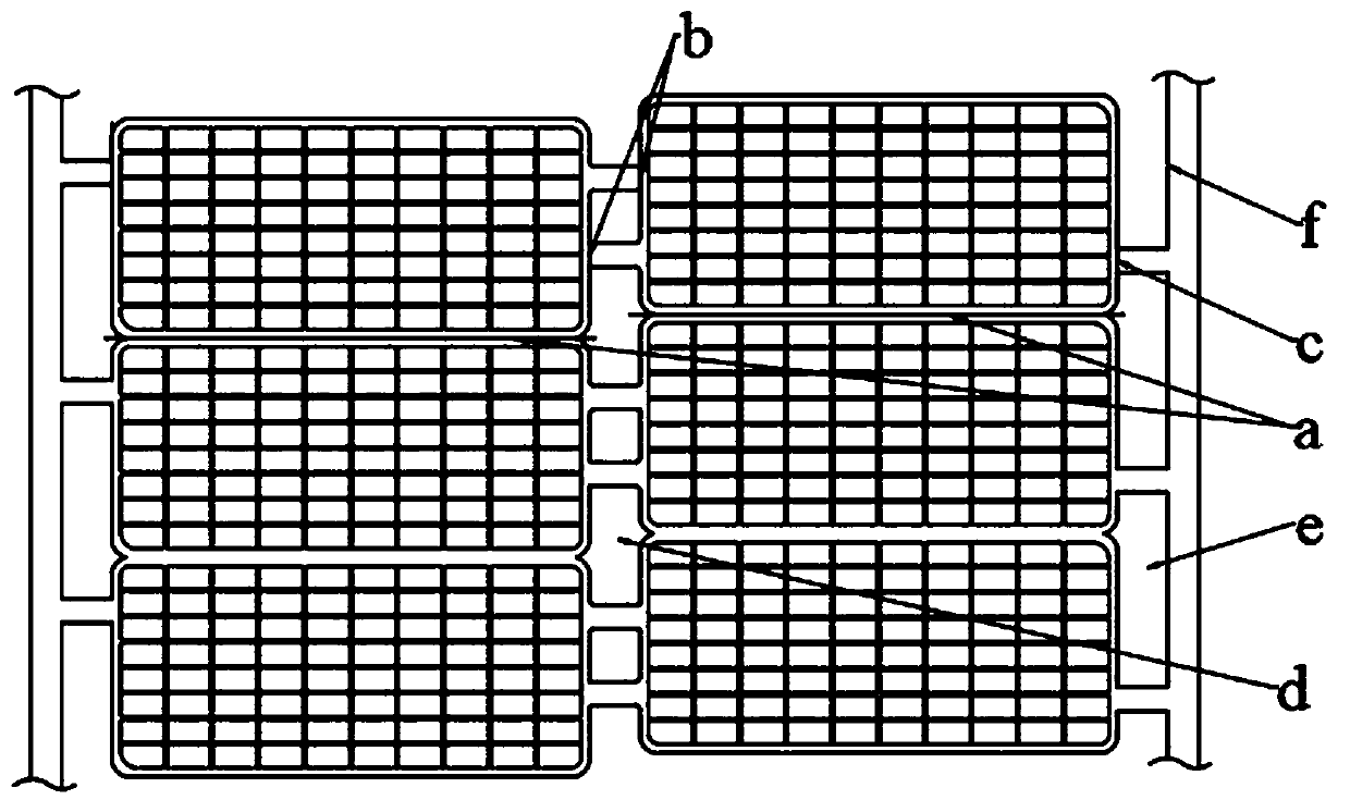
[0045] The continuous grid cut by the grid slicing device is as follows: figure 1As shown, the continuous grid is integrally connected by unit grids, the unit grids are distributed in two rows, the tabs of the grid are located between the grid frames of the two rows, and the two sides of the continuous grid are integrally connected with process connection strips f, cut along the tangent line a between the frame, the tangent line b of the tab and the tangent line c of the grid connecting strip (a is the tangent line in the width direction, b and c are the tangent lines in the extending direction of the continuous grid), and you can get Uniformly shaped cell grids. The first positioning hole d is formed by the grid and the pole lug, and the second positioning hole e is formed by the process connecting strip and the same row of grids. The distribution of unit grids in continuous grids and the orientation of tabs can be adjusted based on actual needs.

[0046] Such as Figure 2...

Embodiment 2

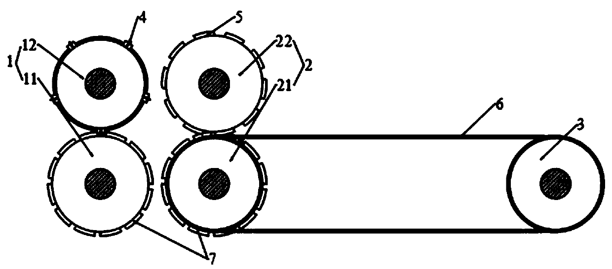
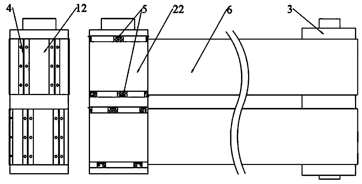
[0053] Such as Figure 7-8 As mentioned above, Embodiment 2 is based on the grid slicing device and the continuous grid of Embodiment 1. The difference is that six grooves 8 are arranged on the surface of the second traction roller 22 in the circumferential direction, and the grid conveyor belts 6 are arranged in cooperation one by one. In the groove 8, three grid conveyor belts 6 are formed into two groups, and are used as bottom brackets to export two rows of unit grids.

[0054] The sharding method includes the following steps:

[0055] S1: Lead the continuous grid into the roller gap of the first pair of rollers 1, the positioning protrusion 7 of the first traction roller 11 is socketed with the first positioning hole d and the second positioning hole e of the continuous grid, and the active traction continues Grid feeding, the first cutter roller 12 axial first cutter 4 cuts the tangent line a between the frame of the continuous grid, and the unit grid in the continuous ...


PUM


Abstract

The invention discloses a grid slitting device. The grid slitting device comprises a first pair of rollers, a second pair of rollers and a conveying roller, wherein the first pair of rollers and the second pair of rollers are sequentially arranged in the feeding direction. The first pair of rollers and the second pair of rollers respectively comprise a traction roller and a cutter roller. First cutters are circumferentially arranged at intervals on the cutter roller of the first pair of rollers. Second cutters are circumferentially arranged at intervals on the cutter roller of the second pairof rollers. Blades of the first cutters extend in the axial direction of the corresponding cutter roller and used for slitting a continuous grid along slitting lines in the belt width direction. The second cutters comprise longitudinal cutters, and blades of the longitudinal cutters extend in the circumferential direction of the corresponding cutter roller and used for slitting the continuous gridalong slitting lines in the extending direction. A grid conveyor belt is wound round the conveying roller and the traction roller of the second pair of rollers, and the conveyor belt and the blades of the second cutters are staggered in the axial direction of the corresponding traction roller. By the adoption of the grid slitting device, the continuous grid is cut by the rollers twice, and compared with grids obtained through one-time roller cutting operation in the prior art, slit unit grids can directly fall to the grid conveyor belt, and the unit grids are discharged in order.

Description

technical field [0001] The invention relates to the technical field of lead-acid battery grid production equipment, in particular to a grid slicing device and a slicing method. Background technique [0002] The grid is the main component of the lead-acid battery. It is the current collector skeleton of the electrode, which plays the role of conducting, collecting and making the current evenly distributed. At the same time, it supports the active material and is the carrier of the active material. The continuous casting and rolling method is one of the main methods of grid production. The specific process is: continuous casting and rolling of lead liquid into lead strips of a certain width and thickness, punching holes on the lead strips to support continuous grids, and then cutting A continuous grid; or coating a lead paste containing an active material on the continuous grid, drying to obtain a continuous pole plate, and cutting the continuous pole plate. [0003] The slic...

Claims


Application Information

Patent Timeline
Patent Type & Authority Applications(China)
IPC IPC(8): B23D19/06B23D33/02
CPCB23D19/06B23D33/02
Inventor 王晓陈波王轶
Owner JIANGSU DONGSHUN NEW ENERGY TECH
Why Eureka
Try Eureka