
Marine air layer resistance-reducing and energy-saving device

An energy-saving device and gas layer technology, applied in the direction of ship hull, hull design, ship construction, etc., can solve the problems of restricting, restricting the use of technology, not achieving good energy-saving effect, etc., achieving convenient operation, reducing wetted area, structure compact effect

Active Publication Date: 2020-05-22
CHINA SHIP SCIENTIFIC RESEARCH CENTER (THE 702 INSTITUTE OF CHINA SHIPBUILDING INDUSTRY CORPORATION)
View PDF5 Cites 3 Cited by
  • Summary
  • Abstract
  • Description
  • Claims
  • Application Information

AI Technical Summary

Problems solved by technology

[0003] In the existing technology, there are many measures for energy-saving and emission-reduction technologies for ships, such as sails, solar energy, etc., but none of them have achieved good energy-saving effects, and are restricted by the use environment, which severely limits the use of these technologies on real ships.

Method used


Image

  • Marine air layer resistance-reducing and energy-saving device
  • Marine air layer resistance-reducing and energy-saving device
  • Marine air layer resistance-reducing and energy-saving device

Examples


Embodiment 1

[0049] In the first embodiment, the wedge block 12, the slope structure one 13 and the pressure stabilizing chamber 8 can all be modified and added to the existing hull 10, so as to obtain an air layer drag reduction and energy saving device.

Embodiment 2

[0051] like Figure 7 As shown, the bottom of the hull 10 near the stern is set as a slope structure 2 121, and the slope structure 2 121 is inclined downward toward the direction of the stern; as Figure 8 As shown, a step 131 is provided on the bottom of the hull 10 near the bow, and the bottom of the front part of the step 131 protrudes downward.

[0052] The bottom surface of the hull 10 is composed of inclined plane structure 121, steps 131 and coaming plate 11, partition 111 to form air pockets, thereby locking air bubbles and forming an air layer; When the ship is sailing, the air bubbles are smoothly discharged toward the stern; the step 131 at the bow is used to prevent the gas from escaping from the ship, which is more conducive to the maintenance of the air layer.

[0053] like Figure 10 and Figure 11 As shown, the plenum chamber 8 is welded on the outer bottom surface of the hull 10, the air nozzle 9 is set at the bottom of the plenum chamber 8, and the bottom...


PUM


Abstract

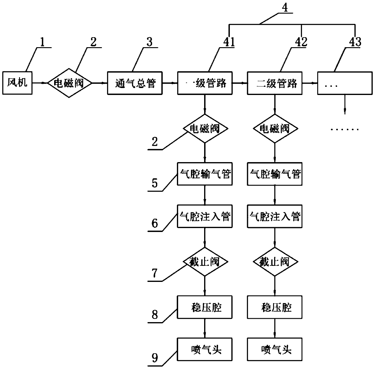
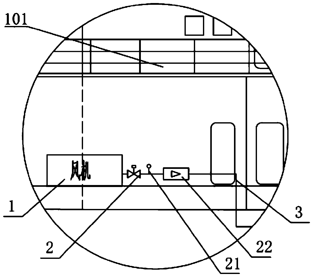
The invention relates to a marine air layer resistance-reducing energy-saving device which comprises a ship body. One or more sets of air supply systems are arranged in the ship body. The output end of a single set of air supply system is connected with a ventilation main pipe, the output end of the ventilation main pipe is sequentially connected with multiple stages of pipelines, and an air cavity air conveying pipe is installed in the front of the joint of every two adjacent stages of pipelines in a penetrating mode. Pressure stabilizing cavities are fixedly formed in the ship bottom of theship body and distributed in parallel in the width direction of the ship body, a plurality of downwards-penetrating air spraying heads are arranged on the pressure stabilizing cavities side by side, and air holes are formed in the outer wall of the ship bottom. The air cavity air conveying pipes convey air into the pressure stabilizing cavities through air cavity injection pipes, and the air is output through the air spraying heads and forms an air layer on the outer wall of the ship bottom. Air is injected between the outer surface of the ship body and water to form uniform and stable gas-liquid two-phase flow, so that the navigation resistance of the ship is reduced, and the propulsion efficiency of the ship is improved. A remarkable application effect can be achieved on resistance reduction and speed increase of a high-speed boat and energy conservation and emission reduction of a large transport ship, and construction of a green and low-carbon ship transport system is effectively assisted.

Description

technical field [0001] The invention relates to the technical field of drag reduction and energy saving of ships, in particular to an air layer drag reduction and energy saving device for ships. Background technique [0002] The shipping industry is a high energy consumption industry. According to incomplete statistics, the world's transport ships consume about 200 million barrels of fuel oil (about 270 million tons) every year, and emit 1.2 billion tons of carbon dioxide, accounting for about 6% of global emissions. For this reason, at the 62nd session of the International Maritime Organization (IMO) Marine Environment Protection Committee (MPEC) held in July 2011, the Energy Efficiency Design Index (EEDI) of new ships was included as a mandatory requirement in the International Convention for the Prevention of Pollution from Ships. "(MARPOL) framework. The mandatory requirements of EEDI have been officially implemented since January 1, 2013, and are divided into four sta...

Claims


Application Information

Patent Timeline
IPC IPC(8): B63B1/38
CPCB63B1/38B63B2001/387Y02T70/10
Inventor 郦羽陈京普高丽瑾魏锦芳恽秋琴阚甜甜程红蓉侯家怡刁峰王伟苗飞邬婷
Owner CHINA SHIP SCIENTIFIC RESEARCH CENTER (THE 702 INSTITUTE OF CHINA SHIPBUILDING INDUSTRY CORPORATION)
Learn More