Rotational flow well shaft wall vibrating device and pouring and vibrating construction method

A technology for pouring and vibrating and construction methods, which is applied in construction, artificial islands, water conservancy projects, etc., can solve the problems of inaccurate control of vibrating spacing, frequent insertion and removal of vibrating rods, and poor vibrating effect.

Inactive Publication Date: 2020-05-22
CHINA 22MCC GROUP CORP
View PDF8 Cites 1 Cited by
  • Summary
  • Abstract
  • Description
  • Claims
  • Application Information

AI Technical Summary

Problems solved by technology

[0004] The technical problem to be solved by the present invention is that the vibrating rod in the primary vibrating range of the existing vibrating device not only needs to adjust its position along the length direction of the well wall, but also needs to change its position on the width of the well wall to supplement the vibrating range. Frequent pulling, inaccurate control of vibrating spacing, and poor vibrating effect

Method used


Image

  • Rotational flow well shaft wall vibrating device and pouring and vibrating construction method
  • Rotational flow well shaft wall vibrating device and pouring and vibrating construction method
  • Rotational flow well shaft wall vibrating device and pouring and vibrating construction method

Examples


Embodiment Construction

[0023] The technical solutions of the present invention will be clearly and completely described below in conjunction with the accompanying drawings. Apparently, the described embodiments are some, but not all, embodiments of the present invention. Based on the embodiments of the present invention, all other embodiments obtained by persons of ordinary skill in the art without making creative efforts belong to the protection scope of the present invention.

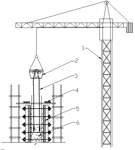
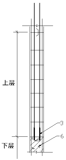
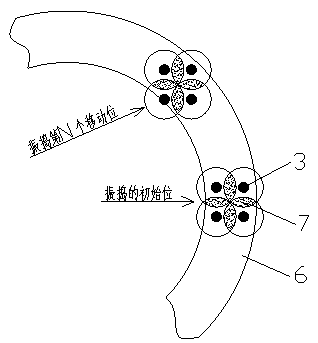
[0024] The invention also provides a construction method for pouring and vibrating the concrete of the wall of the swirl wellbore. Figure 1-4 , and its specific implementation steps are as follows:

[0025] The first step: Install the construction section wall formwork 5 according to the partition of the swirl well, install the construction platform 4 on the top of the formwork, pass the hidden inspection and acceptance, apply for concrete pouring, and do all the preparatory work before pouring.

[0026] Step 2: Set up m...


PUM


Abstract

The invention provides a rotational flow well shaft wall vibrating device. The rotational flow well shaft wall vibrating device comprises four vibrating rods and a distribution box power supply. The distribution box power supply is mounted in a hoisting bucket. The hoisting bucket is fixed below a tower crane. The four vibrating rods are perpendicularly downwards distributed in the shape like a Chinese character 'tian'. Edge weak vibration regions of the four vibrating rods form cross-shaped vibrating overlay regions which have at least one intersection point. The invention further provides arotational flow well shaft wall concrete pouring and vibrating construction method. The construction method comprises the steps of preparing concrete pouring; fixing the multiple vibrating rods in thehoisting bucket, and hoisting the hoisting bucket through the tower crane; evenly pouring the concrete in a layered mode; controlling each vibrating rod to be perpendicularly inserted and pulled backand forth at uniform speed, controlling the insertion space within the vibrating range of the adjacent vibrating rods with the vibrating overlay regions, driving the vibrating rods to conduct synchronous vibrating to enable the vibrating overlay regions to generate the resonance effect; conducting vibrating until no bubbles do not exist on the concrete surface and mortar appears on the concrete surface; and hoisting the vibrating rods to change to a next vibrating region through the tower crane to continue pouring and vibrating.

Description

technical field [0001] The invention belongs to the technical field of swirl well construction, and in particular relates to a concrete pouring device for a swirl shaft wall. Background technique [0002] As we all know, the swirl well is an important building in the field of metallurgical construction, and it is an indispensable structure as a public auxiliary system for steel rolling, steelmaking, and rod and wire. Almost all the swirling wells are circular reinforced concrete structures, with a diameter between 18 and 35 meters, a thick wall generally between 1 and 2 meters, and a buried depth of about 20 to 35 meters. The construction of the swirl well is the key and difficult point in the whole project construction. According to the soil quality, groundwater level and surrounding working conditions, the common construction methods include large excavation, reverse method, caisson and so on. Whether it is large excavation or caisson, the swirling well is divided into se...

Claims


Application Information

Patent Timeline
Patent Type & Authority Applications(China)
IPC IPC(8): E02D29/12E02D15/02E04G21/08
CPCE02D15/02E02D29/125E04G21/08
Inventor 王代发查广民
Owner CHINA 22MCC GROUP CORP
Why Eureka
Try Eureka