
Combustible gas engine

A gas engine and gas technology, used in combustion engines, internal combustion piston engines, gaseous engine fuels, etc., can solve the problems of easy pressure detonation and unbearable engine cylinders, achieve smooth operation, avoid waste, and high resistance to detonation impact effect of ability

Active Publication Date: 2020-05-22
郑州机电工程学校
View PDF7 Cites 0 Cited by
  • Summary
  • Abstract
  • Description
  • Claims
  • Application Information

AI Technical Summary

Problems solved by technology

[0003] At present, there are gradually different forms of engines that use hydrogen and oxygen as fuel and produce water, but these hydrogen-oxygen engines mostly draw on the existing traditional engine form, and compress the hydrogen-oxygen mixture during operation. The chemical properties of hydrogen are relatively active, and it is easy to deflagrate under pressure, and the impact force generated by hydrogen deflagration is more than 20 times that of gasoline of the same volume, which is difficult for the engine block to bear.
In other words, it is difficult for traditional fuel engines to work with hydrogen and oxygen as fuel

Method used


Image

  • Combustible gas engine
  • Combustible gas engine
  • Combustible gas engine

Examples


specific Embodiment 1

[0034] Specific embodiment 1 of the combustible gas engine of the present invention: In this embodiment, hydrogen is used as an example to introduce the structure and working principle of the combustible gas engine of the present invention. Based on the structure of the combustible gas engine of the present invention, in other embodiments, the combustible gas engine of the present invention can also be used as fuel, such as methane.

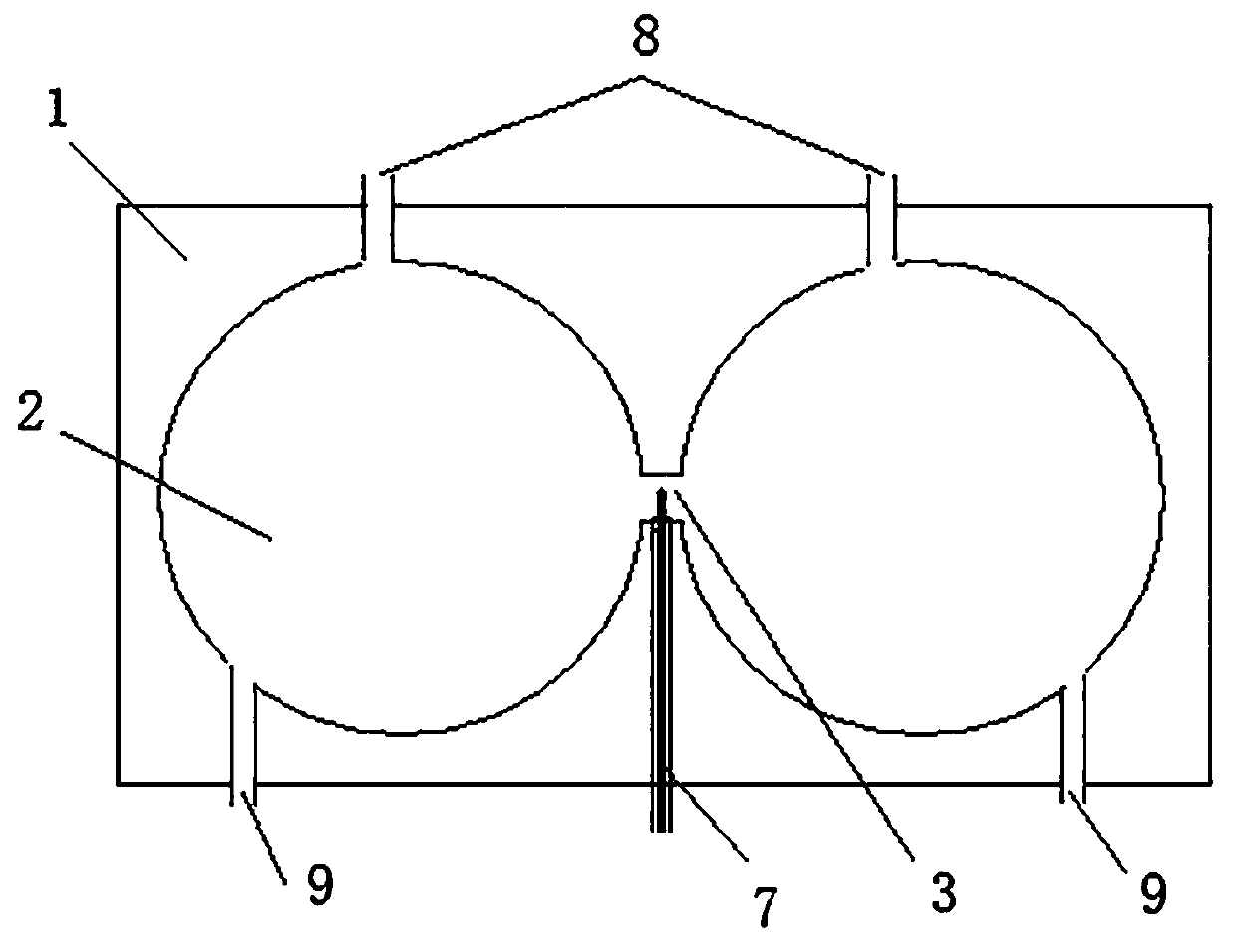
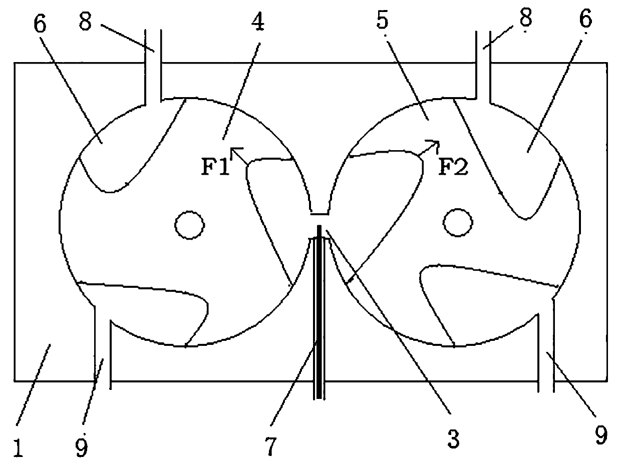
[0035] Such as figure 1 As shown, the combustible gas engine includes a casing 1, and a starting unit is arranged in the casing 1. The starting unit includes a pair of rotating chambers 2 opened on the casing 1, and a communication channel 3 is provided adjacent to the two rotating chambers 2. The communication passage 3 connects the pair of rotating chambers 2 . Such as figure 2 As shown, the engine unit also includes rotors installed in each rotating cavity 2, the axes of the two rotors are parallel and the diameters are equal, and the rotor...


PUM


Abstract

The invention relates to a combustible gas engine. Pairs of rotating cavities are formed in a shell; rotors are rotatably installed in the rotating cavities, and a rotating shaft of at least one rotor is used for outputting torque; the rotors are provided with at least one concave part in the circumferential direction, the concave parts and the corresponding rotating cavities are sealed to form rotor air cavities, and the rotor air cavities are correspondingly filled with combustible gas and oxygen, or are correspondingly used for being filled with the combustible gas and oxygen; when the rotor air cavities formed in the rotating cavities formed in pairs are rotated to the adjacent position of the two rotating cavities, the rotor air cavities are communicated by a communicating channel; and when the rotors are rotated to the position where the rotor air cavities sequentially communicate with an inlet channel, the communicating channel and an exhaust channel, the air inflation, deflagration and exhaust processes are carried out, and the deflagration of the mixed gas drives the rotors to rotate. The rotation of the rotors only changes the position of the rotor air cavities, and thevolume of the rotor air cavities cannot be changed, so that it is ensured that the combustible gas cannot be deflagrated under pressure before reaching the deflagration position, and the stable and reliable operation of the combustible gas engine is ensured.

Description

technical field [0001] The invention relates to a combustible gas engine. Background technique [0002] Since the mechanical revolution, engines based on steam engines and fuel engines have been widely and widely used. However, these two engines use non-renewable mineral energy such as coal and fuel oil as their main energy sources, which brings these two types of engines. Greater limitations. First of all, with the gradual depletion of non-renewable resources such as coal and oil, it will have a great impact on the continued use of steam engines and fuel engines, and secondly, steam engines. When the fuel engine is in use, it emits more harmful gases, which causes great damage to the atmospheric environment. Therefore, based on such problems, people continue to develop new new energy engines to gradually replace traditional steam engines and fuel engines. [0003] At present, there are gradually emerging different forms of engines that use hydrogen and oxygen as fuel and...

Claims


Application Information

Patent Timeline
Patent Type & Authority Applications(China)
IPC IPC(8): F02B53/00F02B53/04F02B53/10F02B55/02F02B55/16F02B43/10
CPCF02B53/00F02B53/04F02B53/10F02B55/02F02B55/16F02B43/10Y02T10/12Y02T10/30
Inventor 王瑞锋秦金龙李恒睿张国福
Owner 郑州机电工程学校
Learn More