Optical imaging lens

An optical imaging lens and lens technology, applied in the lens field, can solve the problems of large edge chromatic aberration, poor distortion control, large object image deformation, etc., and achieve bright pictures, good color reproduction, and small object image deformation Effect

Pending Publication Date: 2020-05-22
XIAMEN LEADING OPTICS
View PDF0 Cites 0 Cited by
  • Summary
  • Abstract
  • Description
  • Claims
  • Application Information

AI Technical Summary

Problems solved by technology

However, the optical imaging lenses currently used in intelligent transportation systems have large edge chromatic aberration and poor color reproduction; when used in high and low temperature environments, the out-of-focus is serious; the distortion control is not good, the object image becomes larger, and the restoration is poor; The light is generally relatively small, and in low-light environments, the incoming light is low, and the shooting picture is dark; and the total length is long, which can no longer meet the increasing requirements of intelligent transportation systems, and urgently needs to be improved.

Method used


Image

  • Optical imaging lens
  • Optical imaging lens
  • Optical imaging lens

Examples


Embodiment 1

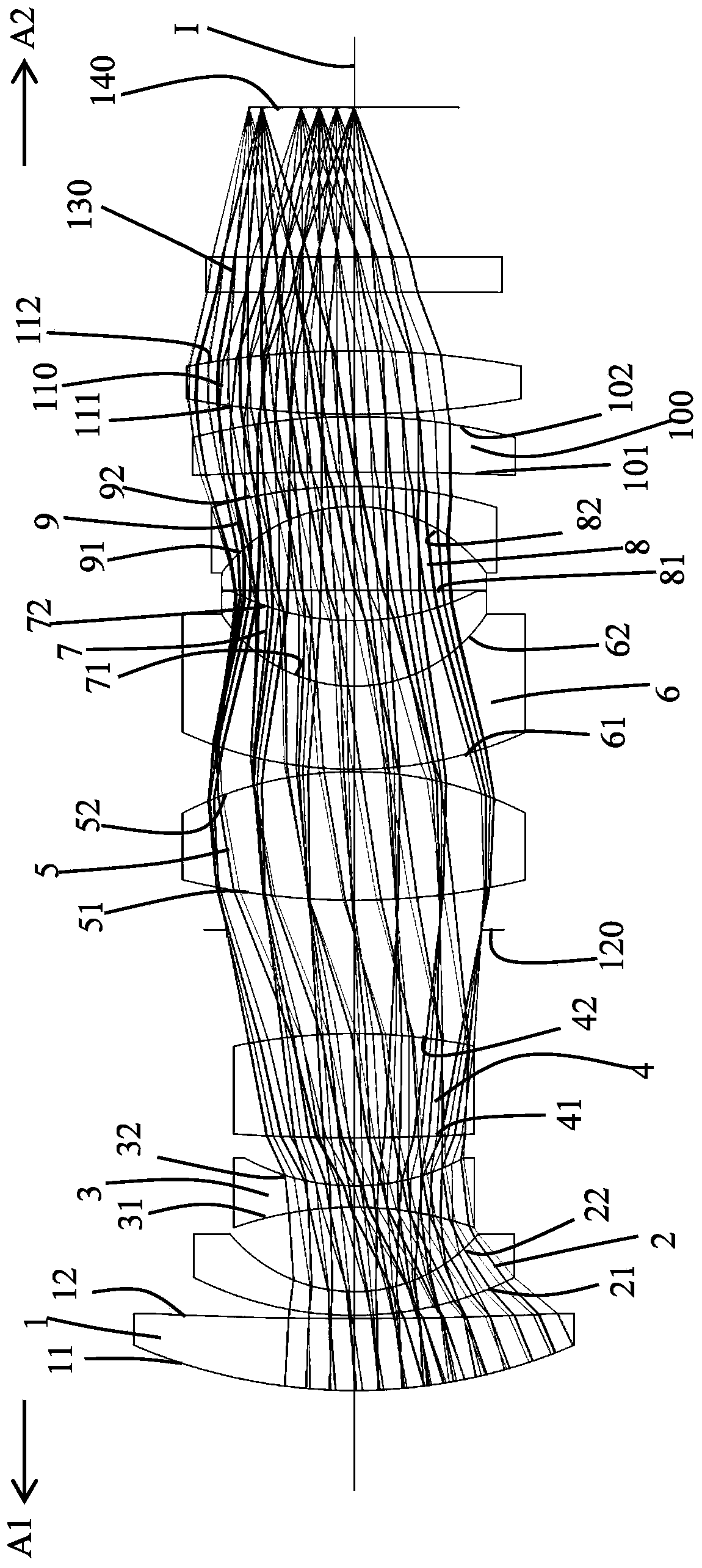
[0094] Such as figure 1 As shown, an optical imaging lens includes a first lens 1, a second lens 2, a third lens 3, a fourth lens 4, a diaphragm 120, and a fifth lens along an optical axis I from the object side A1 to the image side A2. Lens 5, sixth lens 6, seventh lens 7, eighth lens 8, ninth lens 9, tenth lens 100, eleventh lens 110, protective sheet 130 and imaging surface 140; the first to tenth lenses Each of the lenses 110 includes an object side facing the object side A1 and allowing the imaging light to pass therethrough, and an image side facing the image side A2 and allowing the imaging light to pass therethrough.

[0095] The first lens 1 has positive refractive power, the object side 11 of the first lens 1 is convex, and the image side 12 of the first lens 1 is concave.

[0096] The second lens 2 has a negative refractive power, the object side 21 of the second lens 2 is convex, and the image side 22 of the second lens 2 is concave.

[0097] The third lens 3 has...

Embodiment 2

[0116] The concave-convex surface shape and refractive index of each lens in this embodiment are the same as those in the first embodiment, and only the optical parameters such as the radius of curvature of the lens surface and lens thickness are different.

[0117] The detailed optical data of this specific embodiment are shown in Table 2-1.

[0118] Detailed optical data of Table 2-1 Example 2

[0119]

[0120]

[0121] Please refer to the numerical values ​​of the relevant conditional expressions of this specific embodiment Figure 30 .

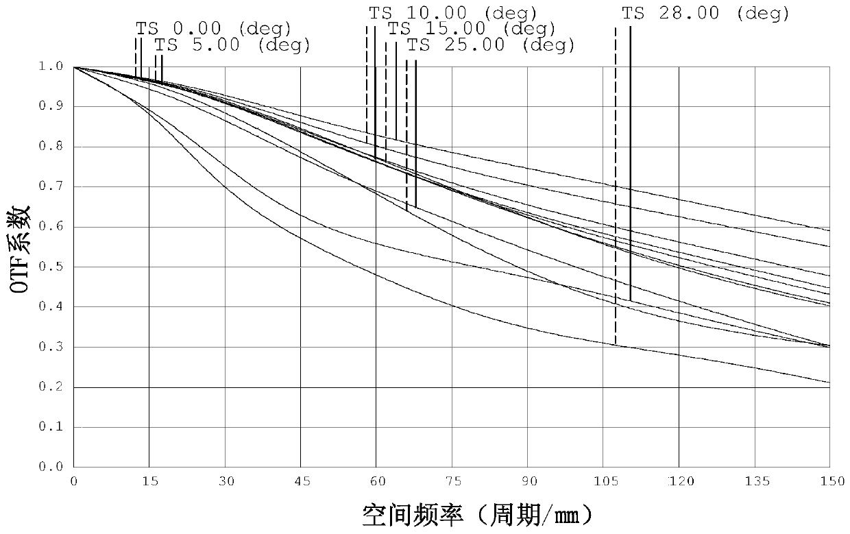
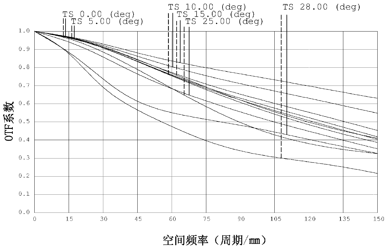
[0122] For the resolution of this specific embodiment, please refer to Figure 9-11 , it can be seen from the figure that the control of the transmission is good, the resolution is high, and the high and low temperature is almost not out of focus; the field curvature and distortion diagram are detailed in Figure 12 (A) and (B), it can be seen that the distortion is small, less than -1%; see the vertical axis aberration diagram fo...

Embodiment 3

[0125] The concave-convex surface shape and refractive index of each lens in this embodiment are the same as those in the first embodiment, and only the optical parameters such as the radius of curvature of the lens surface and lens thickness are different.

[0126] The detailed optical data of this specific embodiment are shown in Table 3-1.

[0127] Detailed optical data of the third embodiment of table 3-1

[0128]

[0129]

[0130] Please refer to the numerical values ​​of the relevant conditional expressions of this specific embodiment Figure 30 .

[0131] For the resolution of this specific embodiment, please refer to Figure 16-18 , it can be seen from the figure that the control of the transmission is good, the resolution is high, and the high and low temperature is almost not out of focus; the field curvature and distortion diagram are detailed in Figure 19 (A) and (B), it can be seen that the distortion is small, less than -1%; see the vertical axis aberra...


PUM


Abstract

The invention relates to the technical field of lenses. The invention discloses an optical imaging lens which comprises eleven lenses and a diaphragm arranged between the fourth lens and the fifth lens. The first lens and the seventh lens are convex-concave lenses with positive refractive indexes; the second lens and the sixth lens are convex-concave lenses with negative refractive indexes; the third lens is a concave lens with negative refractive index; the fourth lens, the fifth lens and the eleventh lens are convex lenses with positive refractive indexes; the eighth lens is a plano-convex lens with a positive refractive index; the ninth lens is a concave-convex lens with a negative refractive index; the tenth lens is a concave-convex lens with a positive refractive index; the sixth lensand the seventh lens are glued to each other, and the eighth lens and the ninth lens are glued to each other. The optical imaging lens has the advantages of small chromatic aberration, small distortion and high imaging quality; the high and low temperature defocusing is small or no defocusing is caused; light transmission is high; and the total length is short.

Description

technical field [0001] The invention belongs to the technical field of lenses, and in particular relates to an optical imaging lens. Background technique [0002] With the continuous advancement of science and technology and the continuous development of society, optical imaging lenses have also developed rapidly in recent years, and are widely used in smart phones, tablet computers, video conferencing, vehicle monitoring, security monitoring, intelligent transportation systems, etc. Therefore, the requirements for optical imaging lenses are getting higher and higher. [0003] In intelligent transportation systems, the performance of optical imaging lenses is critical and will affect the reliability of the entire system. However, the optical imaging lenses currently used in intelligent transportation systems have large edge chromatic aberration and poor color reproduction; when used in high and low temperature environments, the out-of-focus is serious; the distortion contro...

Claims


Application Information

Patent Timeline
Patent Type & Authority Applications(China)
IPC IPC(8): G02B13/00G02B7/02
CPCG02B7/021G02B13/0015G02B13/006
Inventor 李雪慧曹来书
Owner XIAMEN LEADING OPTICS
Why Eureka
Try Eureka