Supercharge Your Innovation With Domain-Expert AI Agents!

LED dispensing method

A dispensing and glue technology, applied in electrical components, circuits, semiconductor devices, etc., can solve problems such as overflowing glue, falling off of LED lights, reducing production efficiency, etc., to achieve the effect of simple process, increased adhesion, and high product yield.

Inactive Publication Date: 2020-05-22
SHENZHEN LONGLI TECH CO LTD
View PDF5 Cites 2 Cited by
  • Summary
  • Abstract
  • Description
  • Claims
  • Application Information

AI Technical Summary

Problems solved by technology

This kind of glue is aligned on the top of the LED chip. Since the slot inside the PPA bracket bowl is lower than the position of the silver plating layer, if the glue is dispensed from a non-slot position, the packaging glue will not flow evenly and appear due to the existence of uneven positions. Glue overflow phenomenon
[0003] In order to solve the above problems, a new dispensing method has emerged, that is, the dispensing head with encapsulation glue is vertically lowered and aligned with the position near the fishing groove in the plastic bracket of the LED chip, and then the glue is controlled, then the dispensing head is raised, and finally moved The dispensing head goes to the position of another LED chip for dispensing operation, but since the dispensing position is close to the position of the plastic bracket, and one-time glue is released at this position, after the glue is discharged, the packaging glue is combined with the side close to the plastic bracket Glue overflow and glue phenomenon will affect the appearance of LED, and glue overflow and glue will cause the problem that the suction nozzle cannot hold the bracket during the subsequent moving of the bracket, reducing production efficiency
[0004] At present, with the thinning and thinning of electronic products, the frame of the backlight module becomes narrower, and the size of the LED at the frame position also becomes smaller.
Insufficient LED adhesion can easily cause the LED lamp to fall off, affecting the brightness and uniformity of the display screen

Method used


Image

  • LED dispensing method
  • LED dispensing method

Examples


Embodiment

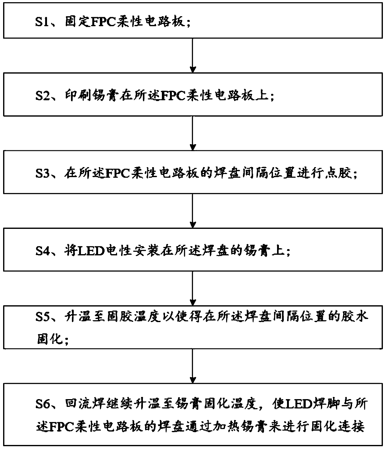
[0028] First, please refer to Figure 1-2 According to the embodiment of the present invention, a method for LED dispensing is provided, which includes the following steps:

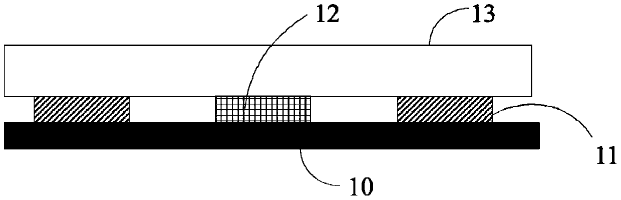
[0029] S1, fixing the FPC flexible circuit board 10;

[0030] S2, printing solder paste 11 on the FPC flexible circuit board 10;

[0031] S3, dispensing glue at the spacing between the pads of the FPC flexible circuit board 10;

[0032] S4, electrically installing the LED 13 on the solder paste 11 of the pad;

[0033] S5, heating up to a curing temperature of 130° C. so that the glue 12 at the position between the pads is cured, and the curing time is 60 s;

[0034] S6. The reflow soldering continues to heat up to the solidification temperature of the solder paste 11 at 230° C., so that the soldering leg of the LED 13 and the pad of the FPC flexible circuit board 10 are cured and connected by heating the solder paste 11 . The curing temperature of the solder paste is higher than the curing temperature...


PUM


Abstract

The invention discloses an LED dispensing method. The LED dispensing method comprises the steps of: S1, fixing an FPC flexible circuit board; S2, printing solder paste on the FPC flexible circuit board; S3, performing dispensing at the interval positions of bonding pads of the FPC flexible circuit board; S4, electrically installing the LED on the solder paste of the bonding pad; S5, raising the temperature to a glue fixing temperature so as to cure the glue at the interval position of the bonding pad; and S6, enabling the reflow soldering to continue to be heated to the solder paste curing temperature, so that the LED welding pins and the bonding pads of the FPC are subjected to curing connection by heating the solder paste. According to the LED dispensing method, the adhesive force of theLED is increased, the process is simple and convenient, the product yield is high, and the LED dispensing method can be used for a backlight source of a narrow-frame backlight module.

Description

technical field [0001] The invention relates to the field of LED package dispensing process, in particular to a method for LED dispensing. Background technique [0002] Existing LED packaging includes: solid crystal, wire bonding, dispensing, light splitting and packaging. The existing dispensing method is to vertically align the dispensing head with packaging glue on the top of the LED chip, then control the glue, and then Move the dispensing head vertically upwards to dispense the next LED chip. This kind of glue is aligned on the top of the LED chip. Since the slot inside the PPA bracket bowl is lower than the position of the silver plating layer, if the glue is dispensed from a non-slot position, the packaging glue will not flow evenly and appear due to the existence of uneven positions. Glue overflow phenomenon. [0003] In order to solve the above problems, a new dispensing method has emerged, that is, the dispensing head with encapsulation glue is vertically lowered...

Claims


Application Information

Patent Timeline
IPC IPC(8): H01L33/54H01L33/62
CPCH01L33/54H01L33/62H01L2933/0066H01L2933/005
Inventor 罗志斌
Owner SHENZHEN LONGLI TECH CO LTD
Features
  • R&D
  • Intellectual Property
  • Life Sciences
  • Materials
  • Tech Scout
  • Unparalleled Data Quality
  • Higher Quality Content
  • 60% Fewer Hallucinations
Learn More