
Relay coil-based constant-current output wireless electric energy compensation network and parameter determination method

A relay coil, constant current output technology, applied in the direction of electrical components, circuit devices, etc., can solve problems such as detuning, cross-coupling, etc., achieve good output characteristics, and eliminate the effect of cross-coupling problems

Pending Publication Date: 2020-05-22
FUZHOU UNIV
View PDF0 Cites 6 Cited by
  • Summary
  • Abstract
  • Description
  • Claims
  • Application Information

AI Technical Summary

Problems solved by technology

[0004] In view of this, the purpose of the present invention is to provide a wireless power compensation network based on relay coil constant current output and a parameter determination method to solve the problems of cross-coupling and detuning in the wireless power transmission system with relay coils

Method used


Image

  • Relay coil-based constant-current output wireless electric energy compensation network and parameter determination method
  • Relay coil-based constant-current output wireless electric energy compensation network and parameter determination method
  • Relay coil-based constant-current output wireless electric energy compensation network and parameter determination method

Examples


Embodiment 1

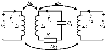
[0089] In this embodiment, for the three-coil wireless power transmission system operating at a frequency of 100kHz, the self-inductance of the transmitting coil of the magnetic coupling structure is 170uH, the self-inductance of the relay coil is 170uH, and the self-inductance of the receiving coil is 240uH, K 1r =0.1197,K r2 =0.4555, K 12=0.1369, relay coil internal resistance R r =1.1Ω, relay coil resonant capacitance C r select The amplitude of the inverter input source connected to the transmitting coil is 100V.

[0090] The inverter input is used as the voltage source, and the compensation is as follows:

[0091] Using the above formula, calculate C s and C p , at this time C s =15.46nF, C p =22.03nF, at this time, the output side can achieve the effect of constant current output amplitude -j6.259A, and it is not affected by the internal resistance of the relay coil and the size of the compensation capacitor. The simulation results are as follows Figure 13-17 ...


PUM


Abstract

Aiming at a wireless electric energy transmission system for three coils, the invention provides a compensation network structure parameter determination method of a three-coil magnetic coupling system containing repeating coils. According to the method, relay coil internal resistance is introduced into a model and then is analyzed, the constant-current output compensation network structure and parameter determination method not influenced by compensation capacitance and internal resistance on a relay coil is obtained, and meanwhile, the problem of cross coupling in a three-coil system is alsoeliminated, so that the system is completely compensated, good output characteristics are obtained, and the method has anti-detuning capability.

Description

technical field [0001] The invention relates to the field of wireless power transmission, in particular to a wireless power compensation network based on relay coil constant current output and a parameter determination method. Background technique [0002] With the rapid development of the electric vehicle industry, people have put forward higher requirements for the safety and convenience of the charging system. Therefore, the contactless charging system of electric vehicles has also been more and more widely used. When the transmission distance increases, the transmission efficiency of the wireless power transmission system decreases rapidly. To solve this problem, inserting a relay coil between the transmitting coil and the receiving coil is a simple, easy, cost-effective and effective way to increase the wireless energy transmission distance. [0003] The introduction of the relay coil provides the possibility of long-distance wireless power transmission, but compared ...

Claims


Application Information

Patent Timeline
Patent Type & Authority Applications(China)
IPC IPC(8): H02J50/12H02J50/50
CPCH02J50/12H02J50/50
Inventor 陈庆彬杨丰钢陈为
Owner FUZHOU UNIV
Learn More