Triboelectric nanogenerator, self-driving vector and direction sensor and its system
A nano-generator and vector sensor technology, applied in the direction of triboelectric generators, can solve the problems that the output signal is susceptible to electromagnetic interference and cannot be used for nonlinear surface sensing, achieves good application prospects, simplifies circuit design, and improves output current. and the effect of voltage
- Summary
- Abstract
- Description
- Claims
- Application Information
AI Technical Summary
Problems solved by technology
Method used
Image
Examples
Embodiment 1
[0087] In a first exemplary embodiment of the present disclosure, a triboelectric nanogenerator with a single charge collection layer is provided.
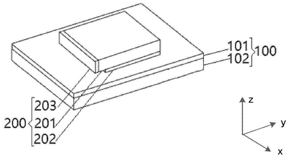
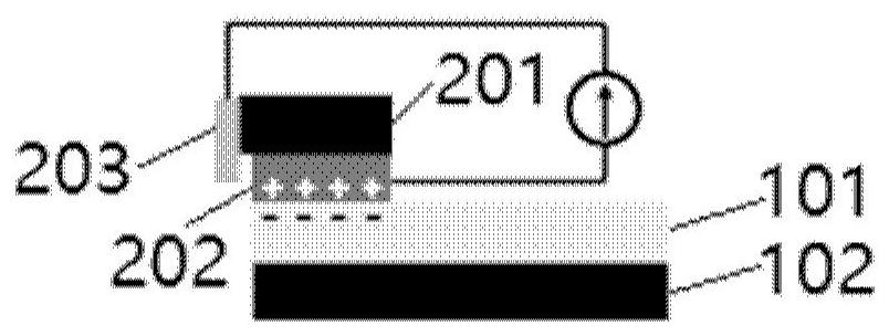
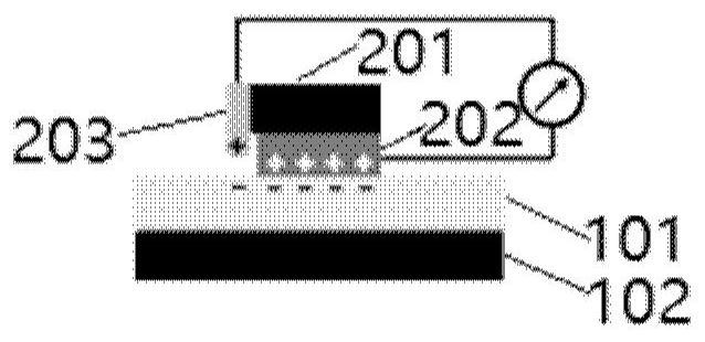
[0088] figure 1 Schematic diagram of the structure of the triboelectric nanogenerator provided in Embodiment 1 of the present disclosure. refer to figure 1As shown, this embodiment provides a triboelectric nanogenerator with a single charge collection layer, which is connected with an external circuit. The triboelectric nanogenerator with a single charge collection layer includes: a first friction unit 100 and a second friction unit 200 .
[0089] The first friction unit 100 of the present disclosure includes a first friction layer 101;
[0090] The second friction unit 200 includes: a second support layer 201; a second friction layer 202 disposed on the side of the second support layer 201 that is in contact with the first friction layer 101; and a charge collection layer 203 disposed on the On at least one side of the second...
Embodiment 2
[0109] In a second exemplary embodiment of the present disclosure, a triboelectric nanogenerator with a double charge collection layer is provided. The difference between the triboelectric nanogenerator of this embodiment and the triboelectric nanogenerator of the first embodiment lies in that the number of charge collection layers is different, and other structures are the same.
[0110] In the triboelectric nanogenerator of the present disclosure, the number of charge collection layers can be extended to 1, 2, 3, 4 or more, for example, in the first embodiment, the second support in the second friction unit 200 The inner layer 201 is a cube structure, including 4 sides, corresponding to 1-4 charge collection layers, which can be respectively arranged on each side of the second support layer of the cube structure, and can be used as a direction sensor to sense the four directions of up, down, left, and right , will be described in detail in subsequent embodiments; or in other...
Embodiment 3
[0117] In a third exemplary embodiment of the present disclosure, a rotational model triboelectric nanogenerator is provided. The structure of this embodiment is further optimized on the basis of the first structure. The shape of the second support layer 201 in the second friction unit 200 is set as a fan shape containing multiple sectors. The corresponding first friction unit 100 The shapes of the first supporting layer 102 and the first friction layer 101 are correspondingly arranged in a disc shape, so that one of the first friction unit 100 and the second friction unit 200 serves as a stator, and the other serves as a rotor, and the two rotate relative to each other. Corresponding to the conversion of mechanical energy generated by sliding friction into direct current, the mechanical energy generated by rotational friction is converted into direct current.
[0118] In some embodiments, one of the first friction unit 100 and the second friction unit 200 serves as a stator, ...
PUM
 Abstract
Description
Claims
Application Information
 - R&D
- Intellectual Property
- Life Sciences
- Materials
- Tech Scout
- Unparalleled Data Quality
- Higher Quality Content
- 60% Fewer Hallucinations
Browse by: Latest US Patents, China's latest patents, Technical Efficacy Thesaurus, Application Domain, Technology Topic, Popular Technical Reports.
© 2025 PatSnap. All rights reserved.Legal|Privacy policy|Modern Slavery Act Transparency Statement|Sitemap|About US| Contact US: help@patsnap.com


