Foot dryer

A technology of a foot dryer and a fan, applied in the field of foot dryers, can solve the problems of cross-infection, cumbersome, inability to guarantee hygiene, etc., and achieve the effects of improving comfort, reducing working noise, and improving the effect of drying feet.

Pending Publication Date: 2020-05-29
DONGGUAN QMS LIGHTING TECH CO LTD
View PDF0 Cites 1 Cited by
  • Summary
  • Abstract
  • Description
  • Claims
  • Application Information

AI Technical Summary

Problems solved by technology

[0002] Usually after taking a shower, people need to find a towel, find a stool, wipe their feet with the towel, and change shoes after drying, which is cumbersome
Moreover, a towel is often used by multiple people, which does not guarantee hygiene and is prone to cross-infection

Method used


Image

  • Foot dryer
  • Foot dryer
  • Foot dryer

Examples


Embodiment 1

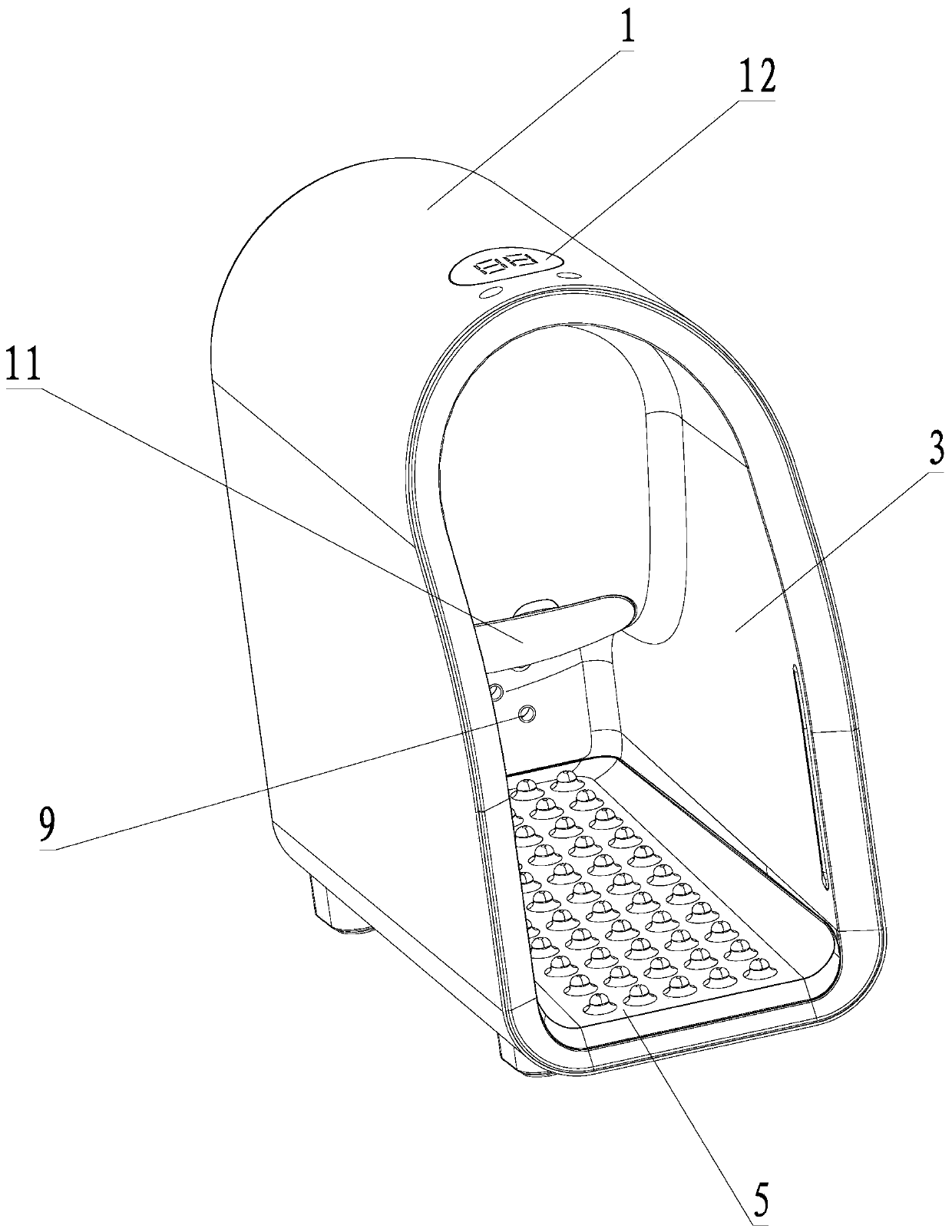
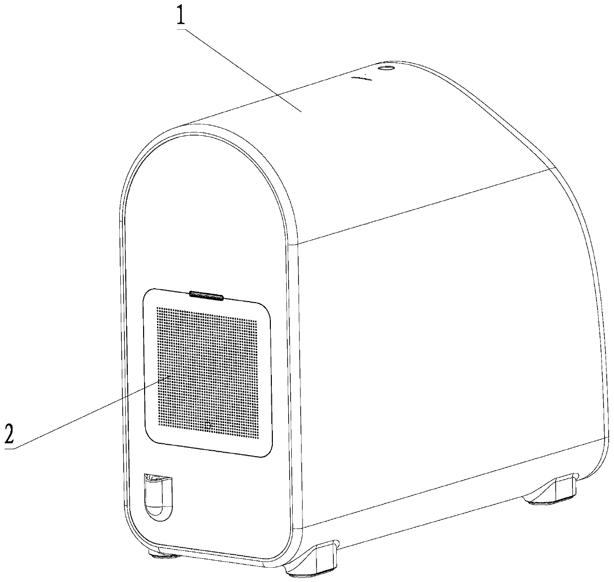
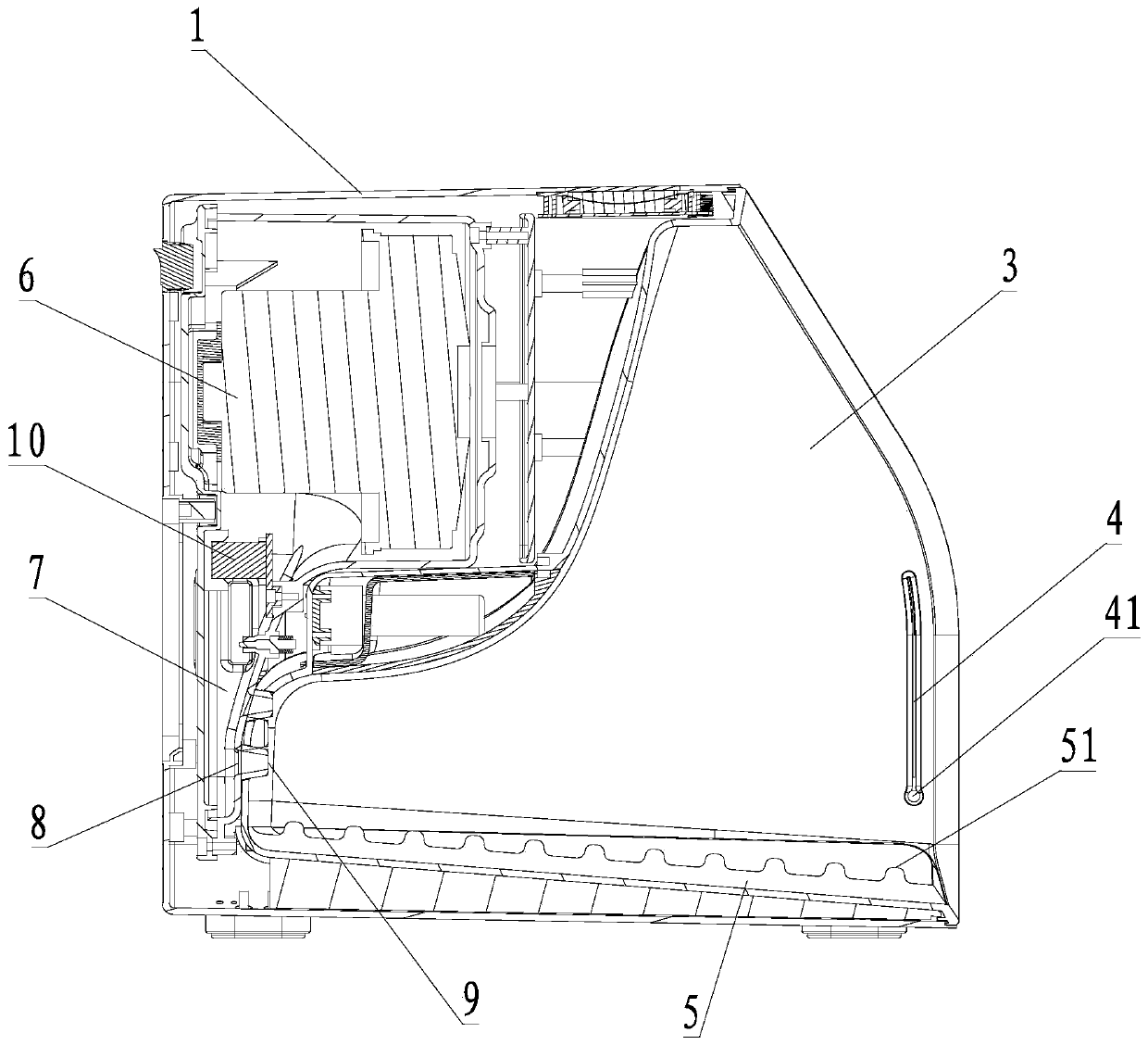
[0022] see Figure 1 to Figure 3 , a foot dryer, comprising a housing 1 and a fan 6, the fan 6 is arranged in the housing 1, the fan includes a fan air inlet for air intake and a fan air outlet for air outlet, The housing 1 is provided with an accommodating cavity 3, the housing 1 is provided with an accommodating cavity opening corresponding to the accommodating cavity 3, and the inner wall of the accommodating cavity 3 is provided with an air outlet 8, and the air outlet 8 The outer side of the housing 1 is provided with an air inlet opening 2, and the air inlet opening 2 is communicated with the fan air inlet through the air inlet channel. The accommodating chamber 3 The bottom surface is provided with a soft foot pad 5.

[0023] In this embodiment, the housing of the foot dryer is provided with an accommodating cavity for accommodating the feet, and an opening of the accommodating cavity is provided on the outside of the housing corresponding to the accommodating cavity, ...

Embodiment 2

[0031] On the basis of Example 1, the soft foot pad 5 is made of silica gel.

[0032] In this embodiment, the silica gel material has stable chemical properties, good thermal stability, and high mechanical strength, and the silica gel has a certain self-cleaning function, is not easy to be stained, and is easy to clean. A softer touch, on the other hand, can improve the anti-slip performance of the foot pad.

Embodiment 3

[0034] On the basis of Embodiment 2, the soft foot pad 5 is provided with elastic protrusions 51 .

[0035] In this embodiment, the elastic protrusions can provide elastic support for the foot pad, which can provide a more comfortable touch and effectively improve user experience.


PUM


Abstract

The invention provides a foot dryer comprising a shell and a fan. The fan is arranged in the shell, the shell is provided with a containing cavity, the shell is provided with a containing cavity opening corresponding to the containing cavity, the inner wall of the containing cavity is provided with an air outlet, the air outlet is communicated with an air outlet of the fan through an air outlet duct, the outer side of the shell is provided with an air inlet opening, the air inlet opening is communicated with an air inlet of the fan through an air inlet duct, and soft foot pads are arranged atthe bottom of the containing cavity. The foot dryer has the following beneficial effects: the foot dryer is simple in structure and convenient to use; the air outlet in the cavity is used for impacting the foot surface and the tangential force, generated by the airflow impact, of the feet is increased, so that water spots on the foot faces are blown off, the foot drying time is effectively shortened, the foot drying effect is improved; the pneumatic noise at the air outlet is effectively lowered through the design of the air outlet, so that the working noise of the foot dryer is lowered; the comfort degree is improved in cooperation with a soft foot pad at the bottom, so that the user experience is greatly improved.

Description

technical field [0001] The invention relates to the technical field of household appliances, in particular to a foot dryer. Background technique [0002] Usually after taking a shower, people need to find a towel, look for a stool, wipe their feet with the towel, and change their shoes after drying, which is more cumbersome. Moreover, a towel is often used by multiple people, which cannot guarantee hygiene and is prone to cross-infection. In order to reduce these troubles, save drying time, and avoid the risk of mutual infection of bacteria, it is necessary to develop a new air-drying equipment. Contents of the invention [0003] The technical problem to be solved by the present invention is to provide a quick foot drying device that can be clean, fast, safe and comfortable. [0004] In order to solve the above technical problems, the technical solution adopted by the present invention is: a foot dryer, including a housing and a fan, the fan is arranged in the housing, t...

Claims


Application Information

Patent Timeline
Patent Type & Authority Applications(China)
IPC IPC(8): A47K10/48A61N5/06
CPCA47K10/48A61N5/0624A61N2005/0661
Inventor 李国胜
Owner DONGGUAN QMS LIGHTING TECH CO LTD
Why Eureka
Try Eureka