Bottom mud squeezing comprehensive treatment system

A comprehensive treatment and sludge treatment technology, applied in the fields of sludge treatment, water/sludge/sewage treatment, dehydration/drying/concentrated sludge treatment, etc., can solve problems such as high cost, improve treatment effect and reduce treatment cost effect

Pending Publication Date: 2020-05-29
浙江省疏浚工程有限公司
View PDF4 Cites 0 Cited by
  • Summary
  • Abstract
  • Description
  • Claims
  • Application Information

AI Technical Summary

Problems solved by technology

[0003] In the traditional river sludge treatment technology, the sediment is transported by pipeline or tank truck to the sediment treatment yard for post-processing. The yard will excavate the treatment pool, sedimentation tank, and build corresponding buildings to set up the frame However, once a project is completed, it is necessary to restore all the storage yards. In the process of processing some small rivers and small lakes, if each project builds a corresponding storage yard, it will increase high cost

Method used


Image

  • Bottom mud squeezing comprehensive treatment system
  • Bottom mud squeezing comprehensive treatment system
  • Bottom mud squeezing comprehensive treatment system

Examples


Embodiment 1

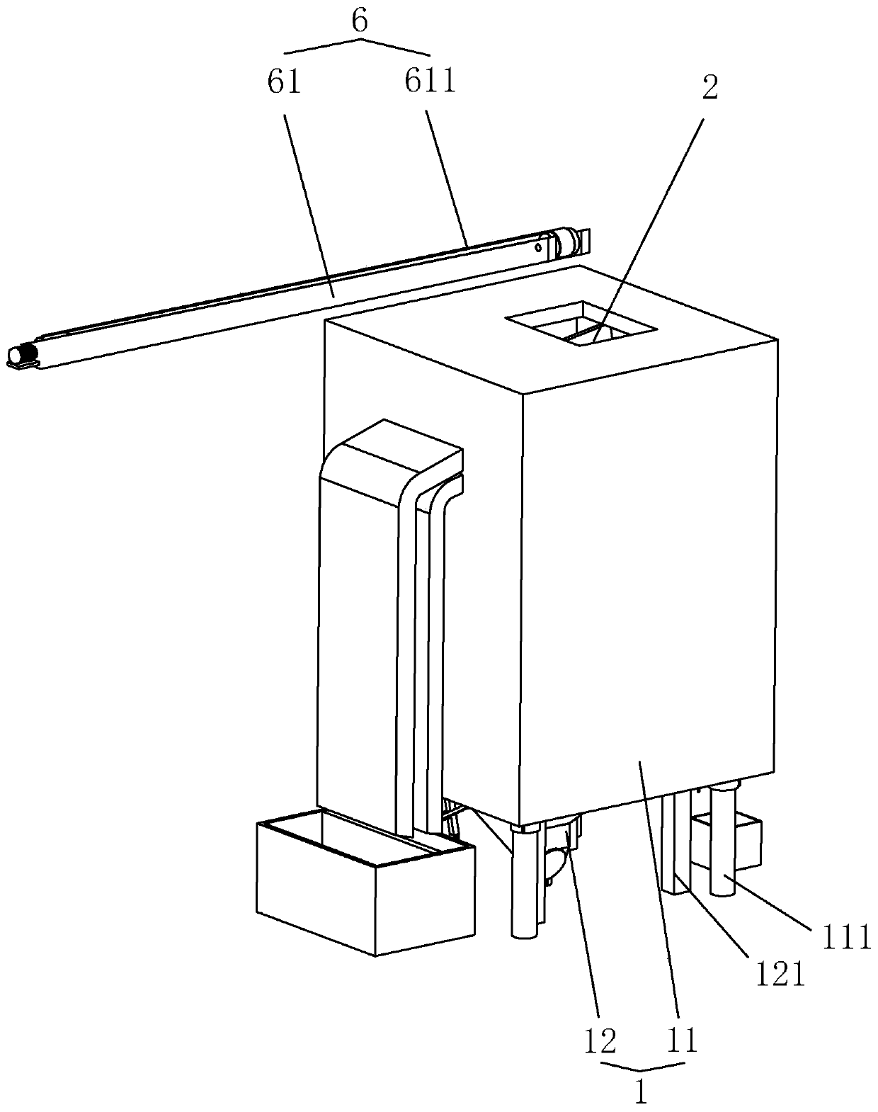
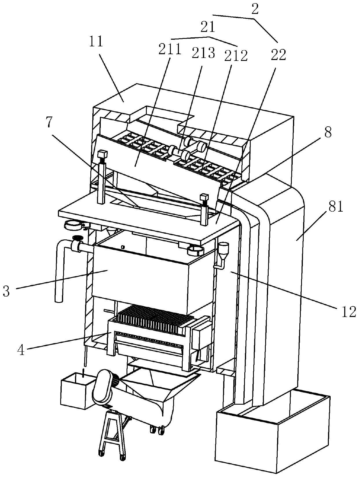
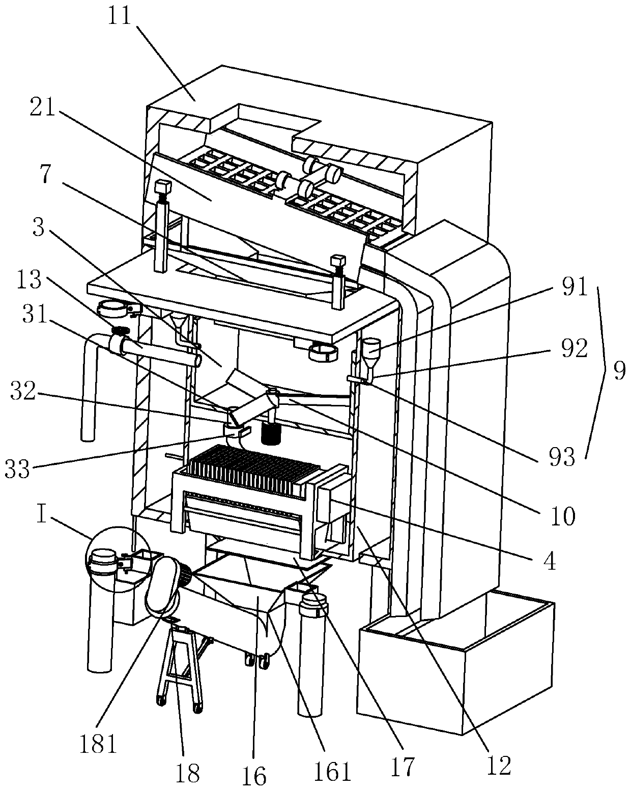
[0033] A comprehensive treatment system for bottom sludge pressing, referring to figure 1 As shown, the processing body 1 is included, the processing body 1 includes a vertical shell 11 with an upper opening, a sand and gravel separation device 2 is arranged on the upper end of the shell 11, and a vertical and independent base 12 is arranged inside the shell 11 , combined with figure 2 As shown, the base 12 is sequentially provided with a sludge treatment tank 3 connected to the sand and gravel separation device 2 and a plate and frame filter press 4 connected to the sludge treatment tank 3 from top to bottom, and a transmission device is provided on the outer wall of the shell 11 6. Relying on the conveying device 6, the sediment at the bottom of the river can be sent in from the upper opening of the casing 11, so as to process the sediment.

[0034] refer to figure 2As shown, the sand and gravel separation device 2 includes a placement plate 22 connected to the upper end...

Embodiment 2

[0041] A bottom sludge pressing comprehensive treatment system, the difference from Embodiment 1 is that in combination with Figure 5 and Figure 6 As shown, the processing main body 1 is provided with multiple groups side by side, and the conveying device 6 also includes a horizontal feeding conveyor 62, and a horizontal feeding belt 621 circulates on the feeding conveyor 62, and the upper end of the feeding conveyor 61 is located at the feeding conveyor 62. Above one end of the belt 621, a material distribution conveyor 63 is slidably connected to the feed conveyor 62 along its length direction. The material distribution conveyor 63 includes a material distribution frame 631 whose length direction is perpendicular to the length direction of the feed conveyor frame. The distribution frame 631 is horizontally mounted above the feeding conveyor 62 . Each of the two ends in the length direction of the distribution frame 631 is connected with a distribution transmission roller ...


PUM


Abstract

The invention discloses a bottom mud squeezing comprehensive treatment system which comprises a treatment main body; the treatment main body comprises a shell and a base; a gravel separation device isarranged at the upper end of the shell; a sludge treatment tank communicated with the gravel separation device and a plate-and-frame filter press communicated with the sludge treatment tank are sequentially arranged in the base from top to bottom; the gravel separation device comprises a high-frequency vibrator fixedly connected to the shell; the base is located in the shell and is independent ofthe shell, the sludge treatment tank and the plate-and-frame filter press are fixed in the base, a connecting mechanism is detachably connected between the base and the shell, a conveying device is arranged on the outer wall of the shell, and the upper end of the conveying device is arranged above an upper opening of the shell. According to the bottom mud squeezing comprehensive treatment system,the position of the treatment main body can be conveniently changed according to actual engineering, and the construction cost is reduced.

Description

technical field [0001] The invention relates to a dredging project, in particular to a bottom sludge pressing comprehensive treatment system. Background technique [0002] With the development of my country's economy and the advancement of urbanization, a large amount of industrial wastewater and domestic sewage generated along the river towns and streets have been discharged into the river. The river has been seriously polluted, seriously damaging the river ecosystem, affecting residents' lives, and endangering human health. At present, the rivers in most cities in our country are polluted to varying degrees, especially in cities with relatively developed industrial development, the pollution is particularly prominent. The pollutants entering the river channel are finally deposited in the bottom mud and gradually enriched to form polluted bottom mud, which is the key endogenous pollutant of rivers and lakes. Dredging is currently the main measure to control the internal so...

Claims


Application Information

Patent Timeline
IPC IPC(8): C02F11/121C02F11/122C02F11/143C02F11/14
CPCC02F11/122C02F11/143C02F11/121C02F11/14
Inventor 卢元均徐岗简明珠朱跃菲向守亮潘骏
Owner 浙江省疏浚工程有限公司
Why Eureka
Try Eureka