Vibrating spring type efficient cotton opening knocking device

A vibrating spring type and high-efficiency technology, applied in the opening and cleaning machine, fiber opening and cleaning machine, etc., can solve the problems of poor effect and low cotton opening efficiency, and achieve high efficiency, good effect, and prevent agglomeration and agglomeration.

Inactive Publication Date: 2020-05-29
王珂欣
View PDF0 Cites 5 Cited by
  • Summary
  • Abstract
  • Description
  • Claims
  • Application Information

AI Technical Summary

Problems solved by technology

[0005] The purpose of the present invention is to provide a vibrating spring type high-efficiency cotton opening knocking device...

Method used


Image

  • Vibrating spring type efficient cotton opening knocking device
  • Vibrating spring type efficient cotton opening knocking device
  • Vibrating spring type efficient cotton opening knocking device

Examples


Embodiment 1

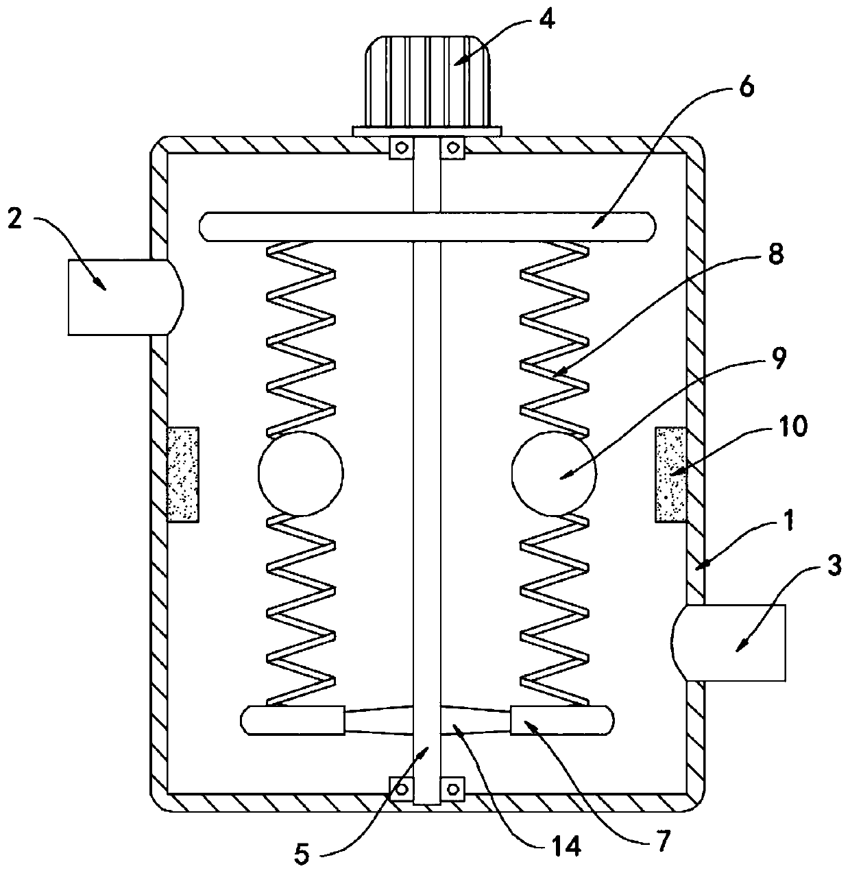
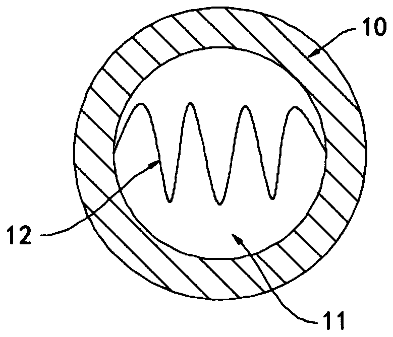
[0020] Such as Figure 1-3 As shown, a vibrating spring type high-efficiency cotton opening knocking device includes a housing 1, a feed pipe 2 and a discharge pipe 3 are fixedly connected to the side walls of the housing 1, and the top surface of the housing 1 is fixedly installed with The motor 4, the output shaft of the motor 4 extends into the casing 1 and is fixedly connected with the rotating shaft 5 coaxially. The casing 1 is respectively provided with an upper support plate 6 and a lower support plate 7 arranged horizontally, and the upper support plate 6 and the lower support plate The plates 7 are all arranged in a disc shape, and the rotating shaft 5 runs through the upper supporting plate 6 and the lower supporting plate 7 in turn and is connected to the inner bottom surface of the housing 1 in rotation. A fan 14 is fixedly installed in the lower supporting plate 7. The shaft is fixedly connected, the rotating shaft 5 is fixedly connected to the upper support plate...

Embodiment 2

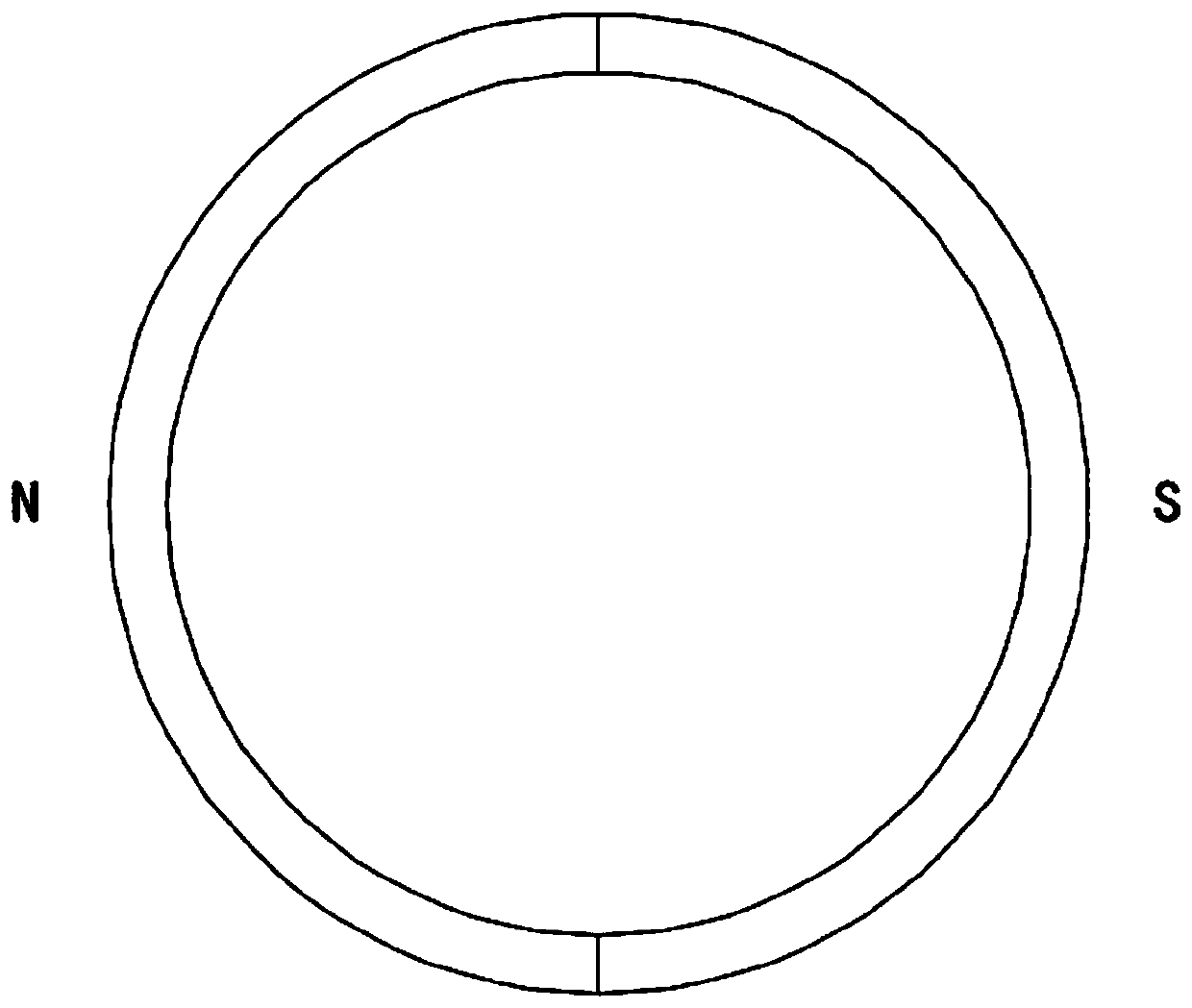
[0024] Such as Figure 4 As shown, the difference between this embodiment and Embodiment 1 is that: the upper support plate 6 is fixedly sleeved with a friction ring 13, the friction ring 13 is made of rubber material, and fur is adhered to the inner wall of the housing 1. The outer wall of the friction ring 13 is in contact with the housing 1 .

[0025] In this embodiment, the motor 4 drives the friction ring 13 to rotate in the housing 1, and the friction ring 13 rubs against the inner side wall of the housing 1. According to the principle of frictional electricity generation, the rubber rod rubbed against the fur will carry a negative charge , then the surface of the friction ring 13 carries a negative charge, which can absorb the dust and impurities in the cotton, thereby playing the effect of dust removal and improving the product quality.


PUM


Abstract

The invention belongs to the technical field of textile machinery, and particularly relates to a vibrating spring type efficient cotton opening knocking device. The device comprises a shell, wherein afeeding pipe and a discharging pipe are fixedly communicated with the side wall of the shell respectively, a motor is fixedly installed on a top surface of the shell, an output shaft of the motor extends into the shell and is coaxially and fixedly connected with a rotating shaft, an upper supporting plate and a lower supporting plate which are horizontally arranged are arranged in the shell respectively, the rotating shaft sequentially penetrates through the upper supporting plate and the lower supporting plate and is rotatably connected with an inner bottom surface of the shell, the rotatingshaft is fixedly connected with the upper supporting plate and the lower supporting plate, a plurality of vibrating springs are fixedly connected between the upper supporting plate and the lower supporting plate, and magnetic flapping balls are fixedly installed on the vibrating springs. The cotton opening knocking device disclosed by the invention can drive the magnetic flapping balls to performhigh-frequency knocking on the cotton in the shell through the high-frequency vibration of the vibrating springs, the cotton opening effect is good, the efficiency is high, and a heating coil is closed to heat and dehumidify the cotton, thereby preventing the cotton from absorbing moisture in air and being agglomerated.

Description

technical field [0001] The invention belongs to the technical field of textile machinery, and in particular relates to a vibrating spring type high-efficiency cotton opening knocking device. Background technique [0002] Cotton has good thermal performance and is widely used in textiles. However, cotton is in a ball state after being picked and needs to be processed to make the cotton in an open state. [0003] However, it is usually done by beating the cotton with a beating device. The traditional beating device uses a cam structure to control rod parts to swing along the axis to complete the beating process on the cotton. This processing form has a complicated structure. The cotton beating operation is relatively stiff, the cotton opening efficiency is low and the effect is poor, and the cotton has a strong water absorption capacity, which is easy to absorb moisture in the air and agglomerate, which increases the difficulty of opening the cotton, resulting in the fluffy co...

Claims


Application Information

Patent Timeline
IPC IPC(8): D01G9/12D01G9/14
CPCD01G9/12D01G9/14
Inventor 王珂欣张瑞雯
Owner 王珂欣
Why Eureka
Try Eureka