Numerical control setting machine

A sizing machine and sizing mechanism technology, applied in the direction of sizing/elongation circular fabrics, textiles and papermaking, fabric surface trimming, etc., can solve problems such as not meeting high-quality sizing requirements, affecting sizing quality, and large sizing cavity length, etc. It achieves the effect of simple structure, small temperature difference in shaping and improvement of shaping quality

Pending Publication Date: 2020-05-29
ZHEJIANG NEU MACHINERY EQUIP CO LTD
View PDF1 Cites 2 Cited by
  • Summary
  • Abstract
  • Description
  • Claims
  • Application Information

AI Technical Summary

Problems solved by technology

[0002] Existing tubular fabric sizing equipment, such as the Chinese invention patent with the application number 201710459400.2 discloses a seamless small cylindrical fabric sizing machine, including a frame, a controller and a sizing cavity arranged on the frame. There is a turntable arranged horizontally on the rotating shaft, one side of the turntable is set close to the shaping cavity, and a plurality of shaping frames perpendicular to the turntable surface are arranged along the circumference of the turntable. The shaping frame includes fixed rollers and movable rollers parallel to each other. Both the roller and the movable roller can rotate by themselves and the distance between the rollers can be adjusted. The length of the shaping chamber of this type of setting machine is very large, and it can process a large amount of fabrics at a time, but the volume is large and the energy consumption is high. The section of the shaping chamber is curved, and the temperature difference between the upper and lower sides is large. , which directly affects the quality of shaping and cannot meet the requirements of high-quality shaping

Method used


Image

  • Numerical control setting machine
  • Numerical control setting machine
  • Numerical control setting machine

Examples


Embodiment 1

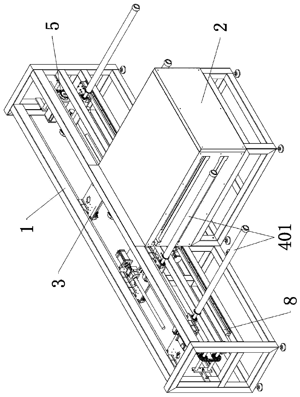
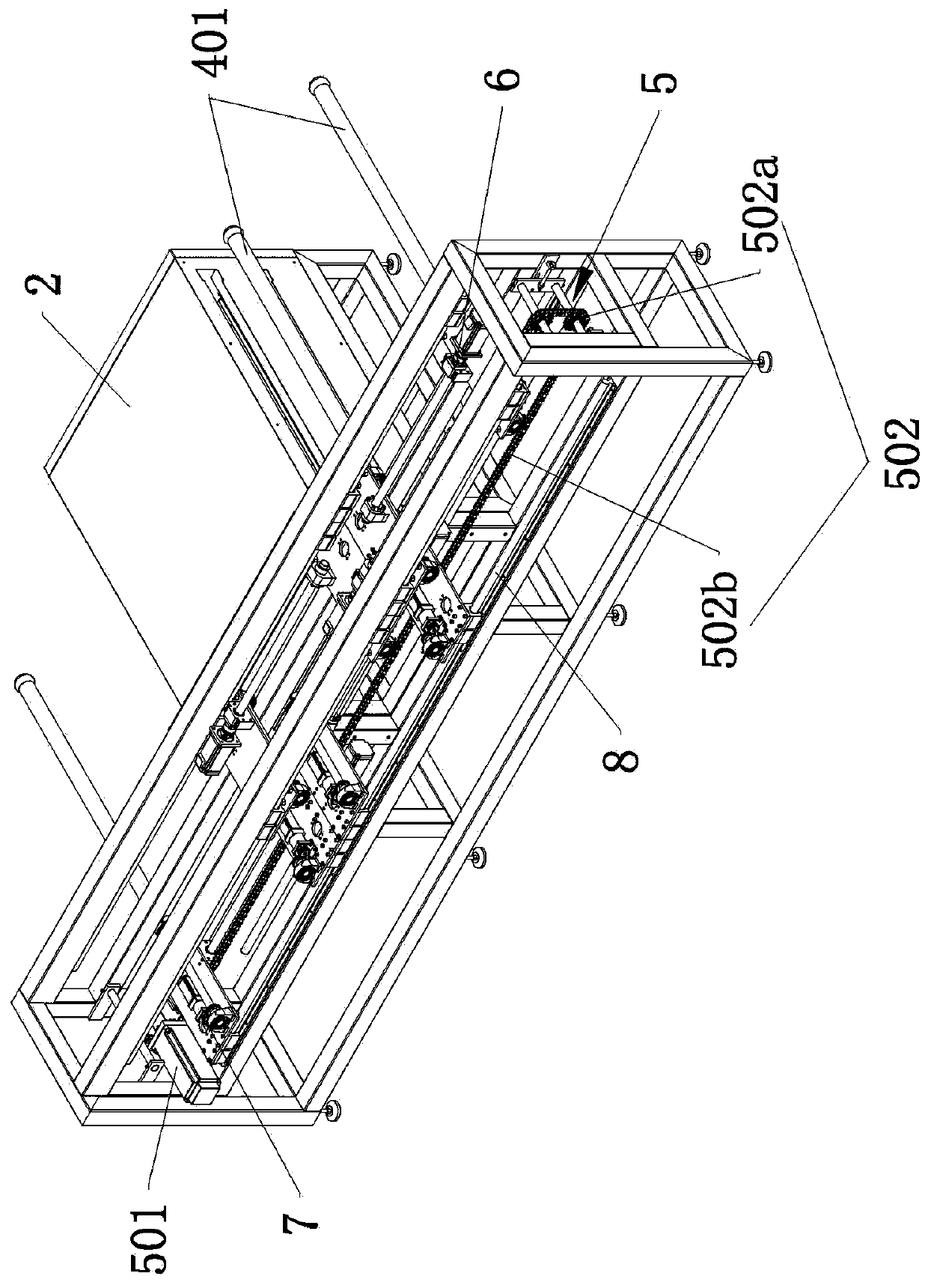
[0025] Example 1: Such as Figure 1 to Figure 5 As shown, a numerical control setting machine includes a setting frame 1, an oven 2 and a setting mechanism 4. The oven 2 is fixedly connected to one side of the setting frame 1, and the setting mechanism 4 and the oven 2 are located on the same side of the setting frame 1.

[0026] The shaping mechanism 4 is divided into upper and lower layers, and each layer of the shaping mechanism 4 includes two sets of shaping components 401, and the two sets of shaping components 401 are arranged front and back. Each group of sizing components 401 includes two sizing rollers 401a, and a total of four sizing rollers 401a of the two groups of sizing components 401 are distributed back and forth along the length direction of the sizing frame 1.

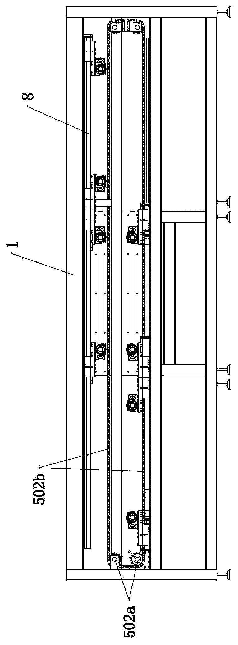
[0027] A movable seat 3 is installed on the sizing frame 1, and the movable seat 3 is installed on the sizing frame 1 through a slide 8 and can move back and forth along the chute 8 in the length direction...

Embodiment 2

[0036] Embodiment 2: The difference from Embodiment 1 is that each layer of the shaping mechanism 4 includes four sets of shaping components 401, and the four sets of shaping components 401 are symmetrically distributed on the left and right sides of the shaping frame 1, that is, the shaping frame 1 There are a total of four shaping rollers 401a for each layer on one side, and two left and right shaping rollers are installed on a movable seat 3. The oven 2 is arranged on the left and right sides of the shaping frame 1 and located in the middle of the shaping frame 1. When the driving assembly 5 is running, The two sets of sizing components 401 corresponding up and down on the same side of the sizing rack 1 alternately enter and exit the oven 2 on the corresponding side.


PUM


Abstract

The present invention relates to a numerical control setting machine. The numerical control setting machine comprises a setting frame, an oven and setting mechanisms, and also comprises moving seats and a driving assembly, wherein the moving seats are mounted on the setting frame through a slideway; the setting mechanisms are mounted on the corresponding moving seats, and the setting mechanisms and the oven are located on a same side of the setting frame; the driving assembly drives the moving seats to move back and forth along the setting frame; and the oven is at least provided with an inletfor the setting mechanisms to enter or leave the oven. The driving assembly controls multiple groups of setting assemblies to enter or leave the oven, so that the number of fabrics subjected to setting by drying in machine operation is increased and the production efficiency is improved; and the front and rear groups of setting assemblies enter or leave the oven alternately to finish setting by drying and replacement of the fabrics alternately, so that the utilization rate of the oven is improved, the width and the volume of the oven are reduced, and the energy consumption of the oven is reduced. The numerical control setting machine is simple in structure, convenient to operate, small in overall volume, low in energy consumption and small in setting temperature difference, and meets thesetting requirement of high quality.

Description

Technical field [0001] The invention relates to the technical field of cylindrical fabric setting equipment, in particular to a numerical control setting machine. Background technique [0002] Existing cylindrical fabric setting equipment, such as the Chinese invention patent application number 201710459400.2 discloses a seamless small cylindrical fabric setting machine, including a frame, a controller and a setting cavity set on the frame. There is a turntable with a rotating shaft arranged horizontally. One side of the turntable is arranged close to the shaping cavity. A plurality of shaping racks perpendicular to the turntable surface are arranged along the circumference of the turntable. The shaping rack includes a fixed roller and a movable roller parallel to each other. Both the roller and the movable roller can rotate and the roller pitch is adjustable. The shaping cavity of this type of shaping machine is very long and can process a large amount of fabrics at a time, but ...

Claims


Application Information

Patent Timeline
Patent Type & Authority Applications(China)
IPC IPC(8): D06C5/00
CPCD06C5/00
Inventor 孙骎周金飞邱延君
Owner ZHEJIANG NEU MACHINERY EQUIP CO LTD
Why Eureka
Try Eureka