Bionic-based compact honeycomb structure heat exchanger core and heat exchanger

A honeycomb structure and heat exchanger technology, applied in indirect heat exchangers, heat exchanger types, heat exchange equipment, etc., can solve problems such as inability to achieve, and achieve the effect of strong adaptability, compact structure, and improved heat exchange power

Active Publication Date: 2022-02-01
陕西益信伟创智能科技有限公司
View PDF7 Cites 0 Cited by
  • Summary
  • Abstract
  • Description
  • Claims
  • Application Information

AI Technical Summary

Problems solved by technology

The most ideal situation is that all heat exchange surfaces are primary heat exchange surfaces, so that the structure of the heat exchanger will become more compact, and it can also play a role in weight reduction; but the existing plate, plate-fin The formula structure cannot achieve this effect

Method used


Image

  • Bionic-based compact honeycomb structure heat exchanger core and heat exchanger
  • Bionic-based compact honeycomb structure heat exchanger core and heat exchanger
  • Bionic-based compact honeycomb structure heat exchanger core and heat exchanger

Examples


Embodiment 1

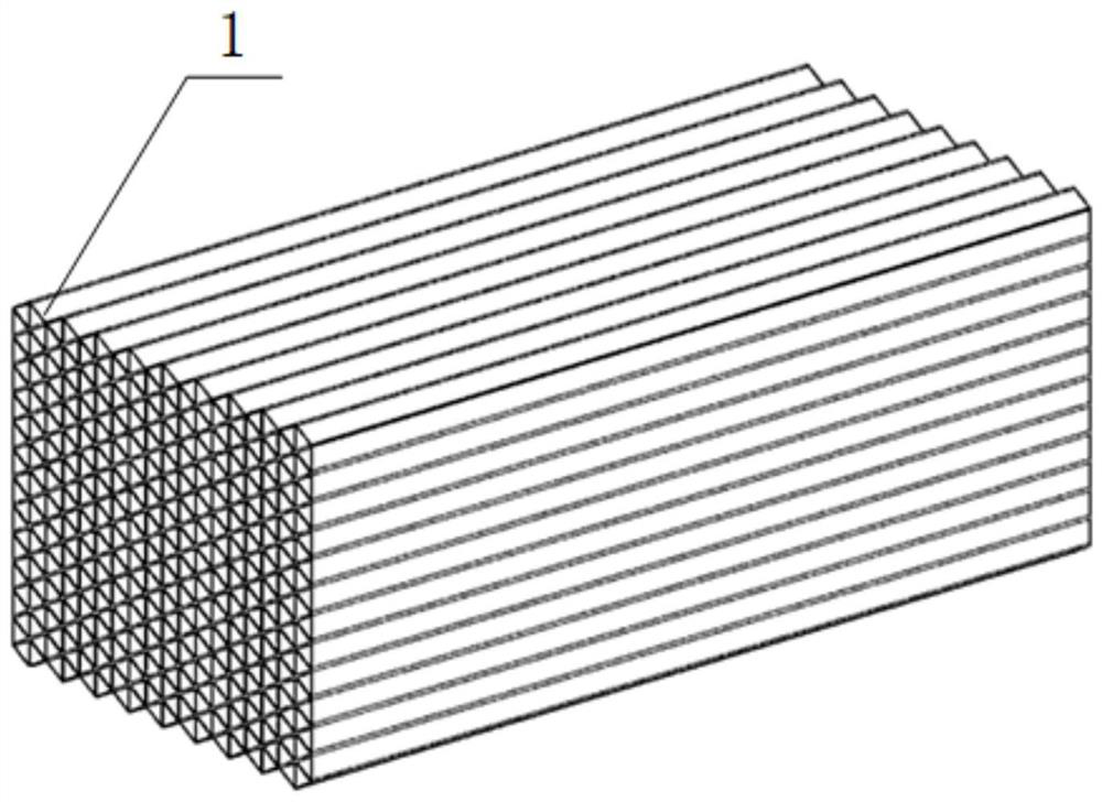
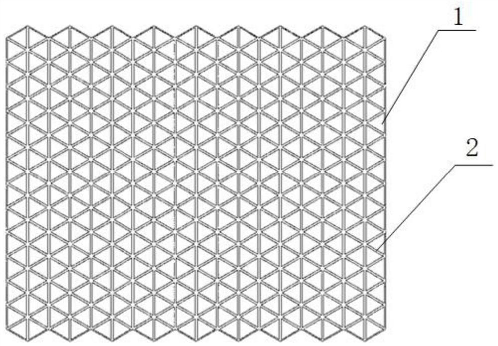
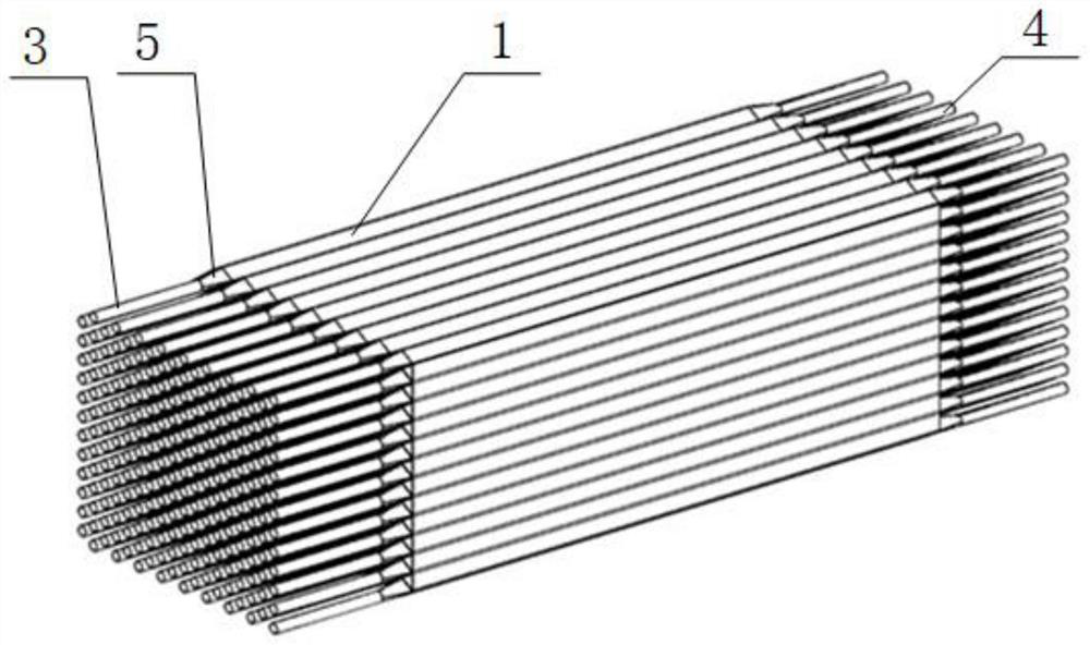
[0044] The embodiment of the present invention is based on a bionic compact honeycomb structure heat exchanger core, such as Figure 1-2 As shown, it includes a plurality of radially spliced ​​straight passages 1, and the outside of the straight passages 1 is provided with a closed shell 8, and the adjacent straight passages 1 respectively pass into the cold medium and the hot medium with opposite flow directions, depending on the medium The straight channel 1 is divided into the first group of straight channels 6 and the second group of straight channels 7, the adjacent first group of straight channels 6 and the second group of straight channels 7 share a wall surface 2, and the first group of straight channels 6 pass through the corresponding The variable diameter adapter pipe 5 communicates with the medium pipeline, and the second set of straight passages 7 communicates with the medium pipeline through the housing 8 . The heat exchange surface between the hot medium and the...

Embodiment 2

[0050] The section of the straight channel 1 is a closed shape composed of straight lines and / or curves. For example, the section of the straight channel 1 is any one of regular triangles, rectangles, regular pentagons, regular hexagons or other polygons, such as Figures 9a-9b As shown, the main body of the cross section of the straight channel 1 is an equilateral triangle, and the three sides are evenly zigzag, which ensures that the flow direction and cross-sectional area of ​​the medium in the core remain unchanged. Compared with the equilateral triangle, the structure increases the unit volume The lower heat exchange area can further increase the heat exchange power per unit mass of the heat exchanger. In addition, in a working environment with a large temperature difference, the heat exchanger will bear a large thermal stress; at this time, the zigzag structure can release the thermal stress through its own elastic deformation, and has better adaptability. The cross-sect...


PUM


Abstract

The invention discloses a bionic-based compact honeycomb structure heat exchanger core and a heat exchanger, comprising a plurality of radially spliced ​​straight passages, a closed shell is arranged outside the straight passages, and adjacent straight passages are The cold medium and the hot medium with opposite flow directions are respectively introduced, and the straight passages are divided into the first group of straight passages and the second group of straight passages according to the different media, and the adjacent first group of straight passages and the second group of straight passages share a wall , the first group of straight passages communicates with the medium pipeline through the corresponding reducing adapter pipes, and the second group of straight passages communicates with the medium pipeline through the housing. The invention has strong adaptability to special-shaped structures, compact structure, and the heat exchange surfaces are all primary heat exchange surfaces, realizing countercurrent heat exchange, good heat exchange performance, high heat exchange per unit weight, and high compressive strength.

Description

technical field [0001] The invention belongs to the technical field of heat exchange equipment, and relates to a bionic-based compact honeycomb structure heat exchanger core and the heat exchanger. Background technique [0002] The heat exchanger uses certain materials and processing techniques to construct heat exchange channels to achieve heat exchange between hot and cold fluids. The structural types of the existing heat exchangers can be roughly divided into two categories, one is the shell-and-tube heat exchanger, and the other is the plate and plate-fin heat exchanger. In the process of realizing the present invention, the inventor has found that there are at least the following problems in the prior art, which are introduced respectively below: [0003] The shell-and-tube heat exchanger is composed of circular tubes, support plates, baffles, shells and other components. The flow form is mostly cross-flow as a whole, and it is difficult to achieve a full sense of coun...

Claims


Application Information

Patent Timeline
Patent Type & Authority Patents(China)
IPC IPC(8): F28D7/00F28F1/02
CPCF28D7/0008F28F1/02
Inventor 罗遥远王俊伟
Owner 陕西益信伟创智能科技有限公司
Why Eureka
Try Eureka