Digital low dropout regulator

A low-dropout voltage regulator, digital technology, applied in the direction of instruments, adjusting electrical variables, control/regulation systems, etc., can solve the problems of reducing circuit robustness and delay unit PVT change sensitivity

Active Publication Date: 2020-05-29
XIDIAN UNIV
View PDF4 Cites 13 Cited by
  • Summary
  • Abstract
  • Description
  • Claims
  • Application Information

AI Technical Summary

Problems solved by technology

Since this structure does not use a clock signal, it greatly reduces power consumption and enhances transient response, but the delay

Method used


Image

  • Digital low dropout regulator
  • Digital low dropout regulator
  • Digital low dropout regulator

Examples


Example Embodiment

[0043] The present invention will be described in further detail below in conjunction with specific examples, but the embodiments of the present invention are not limited thereto.

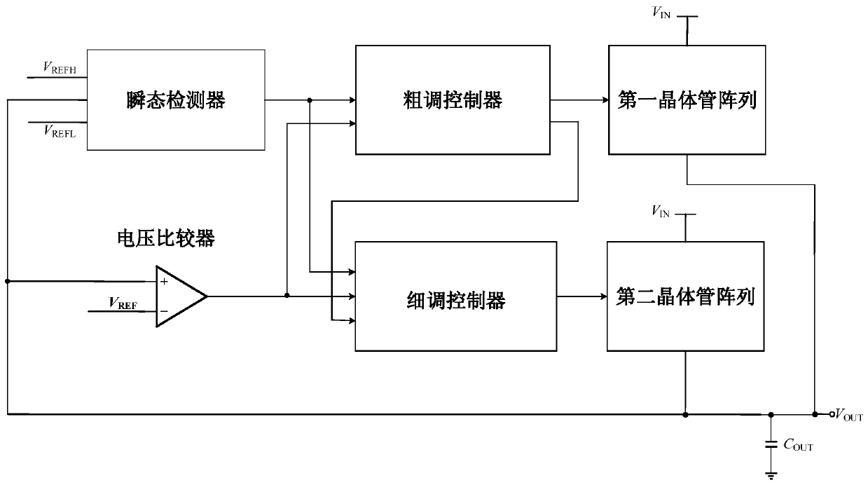
[0044] See figure 2 , figure 2 It is a schematic structural diagram of a digital low dropout voltage regulator provided by an embodiment of the present invention, including:

[0045] Voltage input terminal V IN ;

[0046] Voltage output terminal V OUT ;

[0047] The first reference voltage input terminal V REF ;

[0048] The second reference voltage input terminal V REFH ;

[0049] The third reference voltage input terminal V REFL ;

[0050] A voltage comparator, the inverting input terminal of the voltage comparator is connected to the first reference voltage input terminal V REF , used to input the first reference voltage; the non-inverting input terminal of the voltage comparator is connected to the voltage output terminal V OUT , for receiving the output voltage; the comparison si...


PUM


Abstract

The invention belongs to the field of voltage stabilizers, the invention relates to a voltage stabilizer and particularly relates to a digital low-dropout voltage stabilizer. The stabilizer comprisesa voltage input end, a voltage output end, a first reference voltage input end, a second reference voltage input end, a third reference voltage input end, a voltage comparator, a transient detector, acoarse adjustment controller, a fine adjustment controller, a first transistor array, a second transistor array and a load capacitor. The stabilizer is advantaged in that a method of combining coarseadjustment and fine adjustment is adopted so that the transient response speed and precision are improved.

Description

technical field [0001] The invention belongs to the field of voltage regulators, and in particular relates to a digital low-dropout voltage regulator. Background technique [0002] With the continuous decline of process size, system-on-chip has become the mainstream of integrated circuit design due to its advantages of low power consumption, high efficiency, and small area. Part of it plays a vital role in the performance of the whole system, and it is of great significance to study on-chip integrated LDO with fast transient response. [0003] Traditional LDOs are analog LDOs that are regulated with high-gain error amplifiers. They have the advantages of high bandwidth, low ripple, fast transient response, and high power supply rejection ratio, making them suitable for applications that are sensitive to power rail noise, such as analog circuits and radio frequency circuits. But at the supply voltage close to the sub-threshold, there is not enough voltage margin to make the...

Claims


Application Information

Patent Timeline
IPC IPC(8): G05F1/56
CPCG05F1/56
Inventor 史江义赵博叶晓伟马佩军
Owner XIDIAN UNIV
Why Eureka
Try Eureka