Oil leakage defect detection method and system

A defect detection and oil leakage technology, which is applied in the direction of detecting the appearance of fluid at the leakage point, using liquid/vacuum degree for liquid tightness measurement, image data processing, etc., can solve the problem of high requirements for image acquisition equipment, false alarms, detection The results lack stability and other problems, to achieve the effect of guaranteeing the test results and eliminating the influence

Pending Publication Date: 2020-05-29
SHANTOU UNIV
View PDF5 Cites 9 Cited by
  • Summary
  • Abstract
  • Description
  • Claims
  • Application Information

AI Technical Summary

Problems solved by technology

The process and test results are affected by personal subjective consciousness and experience, resulting in a lack of stability in the test results
[0008] (2) Lack of anti-interference ability to the environment, the fluorescent area in the ph

Method used


Image

  • Oil leakage defect detection method and system
  • Oil leakage defect detection method and system
  • Oil leakage defect detection method and system

Examples


Example Embodiment

[0076] Example 1

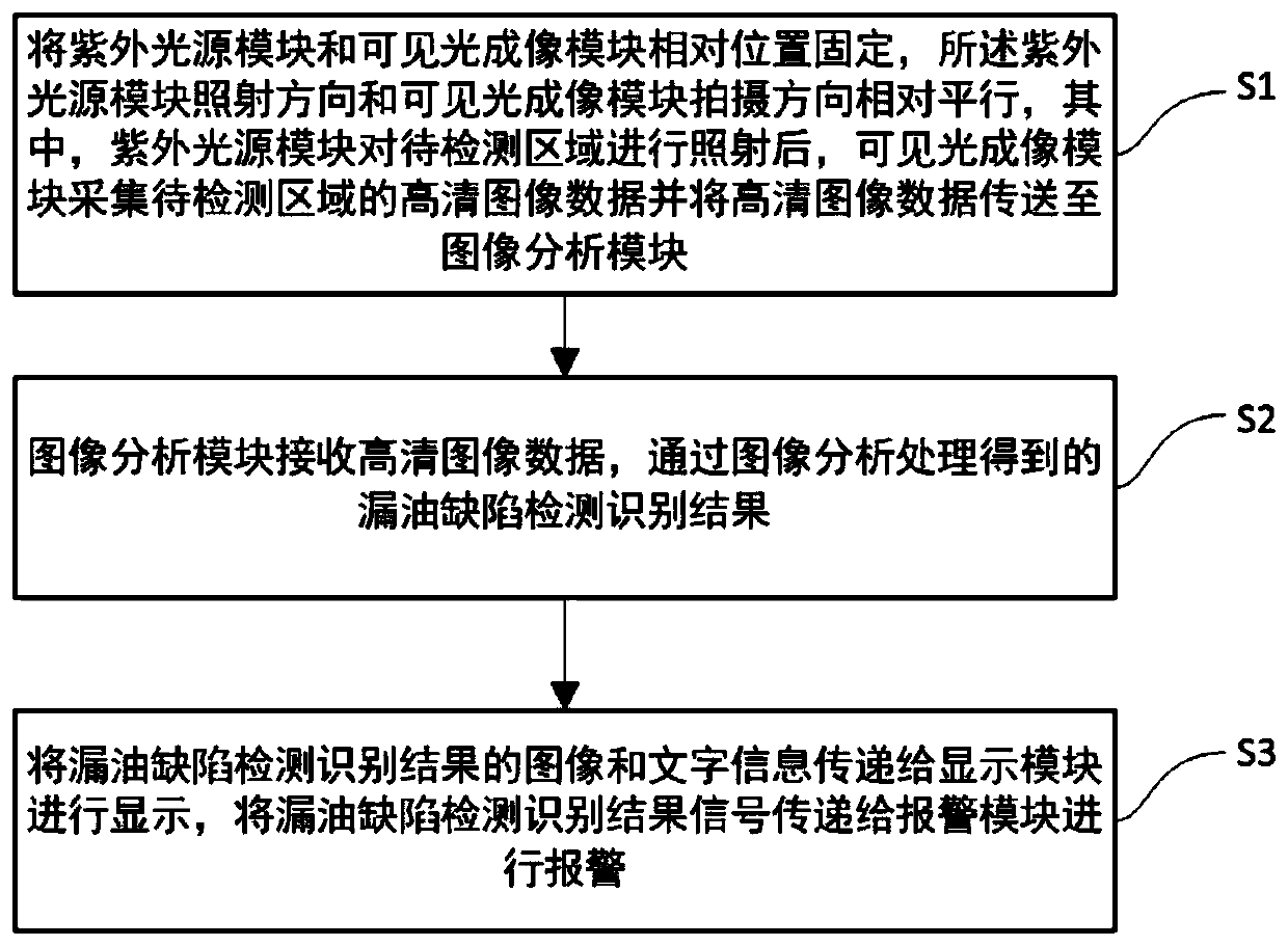
[0077] This embodiment provides a method for detecting oil leakage defects, such as figure 1 , Specifically including the following steps:

[0078] S1: Fix the relative positions of the ultraviolet light source module and the visible light imaging module, the irradiation direction of the ultraviolet light source and the shooting direction of the high-definition camera both face the area to be detected, and the two directions are relatively parallel, wherein the parameter setting module is used to set the parameters of the visible light imaging module After setting, after the ultraviolet light source module illuminates the area to be inspected, the visible light imaging module collects high-definition image data of the area to be inspected and transmits the high-definition image data to the image analysis module;

[0079] S2: The image analysis module receives high-definition image data, and obtains the detection and recognition result of oil leakage through image ...

Example Embodiment

[0120] Example 2

[0121] This embodiment provides an oil leakage defect detection and identification system, such as Figure 4 , Including image acquisition subsystem and information interaction subsystem;

[0122] The image acquisition subsystem includes an ultraviolet light source module and a visible light imaging module;

[0123] The information interaction subsystem includes a parameter setting module, a display module, an alarm module, and an image analysis module;

[0124] The ultraviolet light source module emits ultraviolet light to illuminate the area to be detected;

[0125] The visible light imaging module collects high-definition visible light images of the area to be detected, and transmits the high-definition image data to the image analysis module;

[0126] The parameter setting module is used for the user to set the parameters of the visible light imaging module, the result display setting, and the alarm information setting;

[0127] The display module performs image di...


PUM


Abstract

The invention provides an oil leakage defect detection method and system. The system comprises an ultraviolet light source module, a visible light imaging module, a parameter setting module, a displaymodule, an alarm module and an image analysis module. The method comprises the following steps: S1, fixing relative positions of an ultraviolet light source module and a visible light imaging module,wherein the irradiation direction of the ultraviolet light source module is relatively parallel to the shooting direction of the visible light imaging module, and after the ultraviolet light source module irradiates an area to be detected, the visible light imaging module collects high-definition image data of the area to be detected and transmits the high-definition image data to the image analysis module; S2, enabling an image analysis module to receive the high-definition image data, and obtain an oil leakage defect detection and recognition result through image analysis and processing; S3, transmitting the image and text information of the oil leakage defect detection and recognition result to a display module for display, and transmitting a detection and recognition result signal toan alarm module for alarming. According to the invention, the anti-interference capability of the environment is enhanced, and the influence of personal experience on detection results is avoided.

Description

technical field [0001] The present invention relates to the technical field of oil leakage detection and identification, and more specifically, to an oil leakage defect detection method and system. Background technique [0002] At present, most of the methods for detecting oil leakage use manual patrolling, and require a certain amount of experience to distinguish through artificial "visual inspection" and "nose sniffing". The effect of manual inspection is greatly affected by work experience, and it takes a lot of time and is inefficient. In recent years, fluorescence detection technology has been widely used in the fields of oil exploration and development, monitoring of oil pollutant content in soil, aircraft hydraulic oil leakage and sea surface oil spill monitoring, and a large number of research results have been obtained, which have verified the effectiveness of oil fluorescence detection method. sex. However, there are problems of lack of anti-interference ability ...

Claims


Application Information

Patent Timeline
IPC IPC(8): G06K9/00G06K9/46G06T7/00G06T7/62G06T7/90G01M3/20
CPCG06T7/0002G06T7/62G06T7/90G01M3/20G06T2207/10064G06V20/10G06V10/56
Inventor 吴涛陈贤碧李昌洪李超平徐媛媛
Owner SHANTOU UNIV
Why Eureka
Try Eureka