Ultrasonic atomizing device

A technology of ultrasonic atomization and atomization chamber, which is applied in the field of medical equipment, can solve the problems of lack of reliable solutions and achieve the effects of maintaining efficient operation, controlling occurrence and development, and good use effect

Pending Publication Date: 2020-06-02
SUZHOU INST OF BIOMEDICAL ENG & TECH CHINESE ACADEMY OF SCI
View PDF0 Cites 3 Cited by
  • Summary
  • Abstract
  • Description
  • Claims
  • Application Information

AI Technical Summary

Problems solved by technology

Therefore, the combination of ultrasonic atomization devices and special sterilizing reagents is expected to achieve the inactivation of airborne pathogenic microorganisms, but there is currently a lack of corresponding reliable solutions

Method used


Image

  • Ultrasonic atomizing device
  • Ultrasonic atomizing device
  • Ultrasonic atomizing device

Examples


Embodiment 1

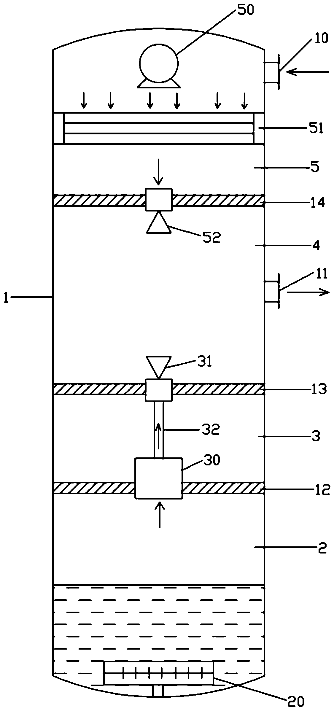
[0038] Such as figure 1 As shown, this embodiment provides an ultrasonic atomization device, including an atomization box 1, an atomization chamber 2, a mist removal chamber 3, a mixing chamber 4, and a heating chamber 5 arranged in the atomization box 1 in sequence from bottom to top, The ultrasonic transducer 20 arranged in the atomization chamber 2, the air pump 30 arranged in the mist removal chamber 3, the mist removal nozzle 31 connected with the air pump 30, the fan 50 and the heater 51 arranged in the heating chamber 5 and the The hot blast in the heating chamber 5 is discharged into the exhaust nozzle 52 in the mixing chamber 4;

[0039] The heating chamber 5 is provided with an air inlet 10, and the mixing chamber 4 is provided with an air outlet 11;

[0040] The atomizing chamber 2 communicates with the mixing chamber 4 through an air pump 30 and a mist discharge spray head 31 , so as to deliver the mist generated in the atomizing chamber 2 to the mixing chamber 4 ...

Embodiment 2

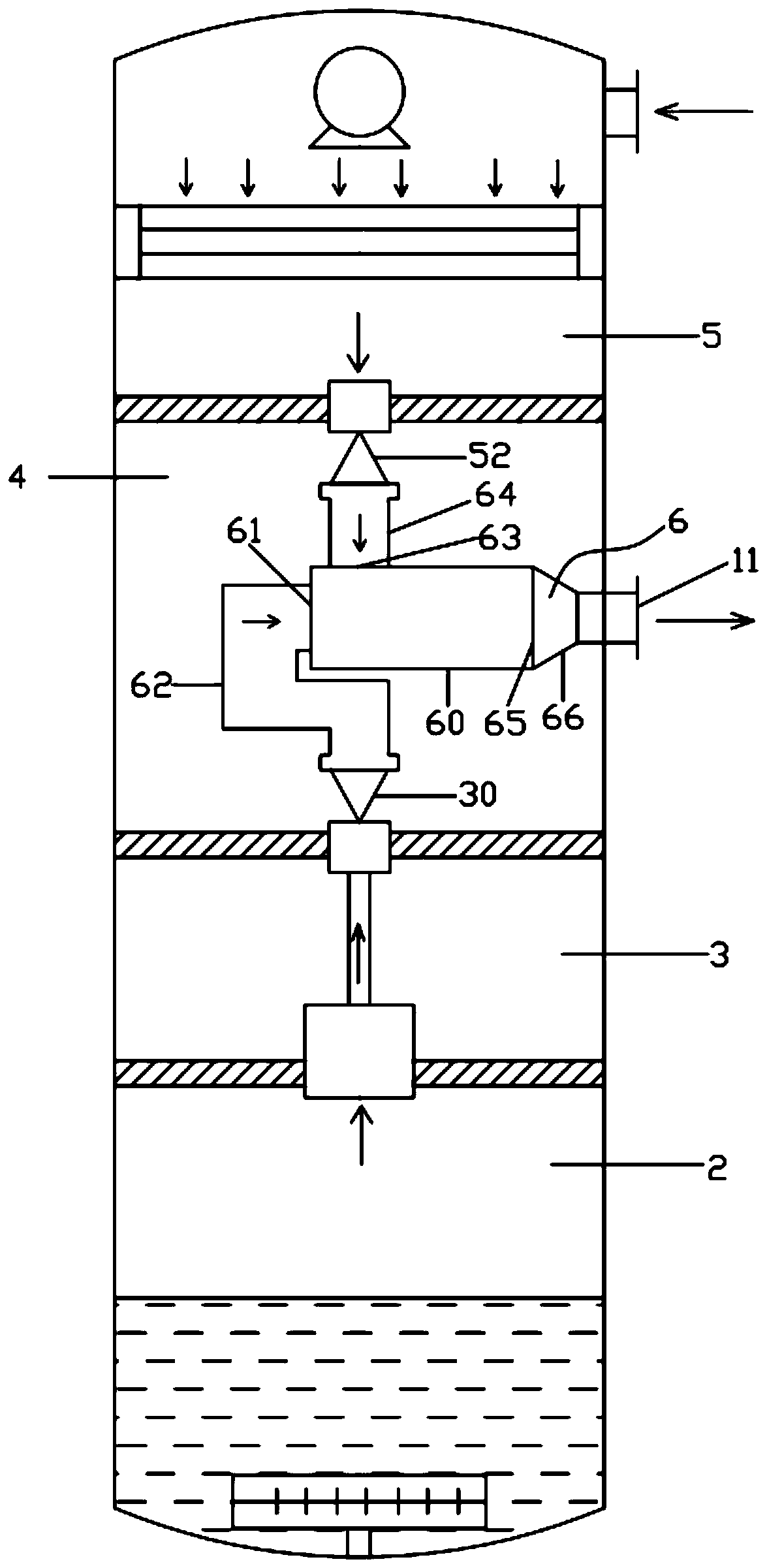
[0050] refer to figure 2 , On the basis of Embodiment 1, further, a diversion mixing assembly 6 is also provided in the mixing chamber 4, and the diversion mixing assembly 6 includes a column guide tube 60, which connects the mist discharge nozzle 31 to the column guide tube The first air inlet pipe 62 of the first air inlet 61 of 60, the second air inlet pipe 64 of the second air inlet 63 connecting the exhaust nozzle 52 to the column air guide pipe 60, and the second air inlet pipe 64 of the column air guide pipe 60 The air outlet 65 is connected to the exhaust pipe 66 of the air outlet 11; the first air inlet 61 is arranged along the axial direction of the column guide tube 60, and the second air inlet 63 is tangentially arranged along the outer peripheral wall of the column guide tube 60 It is provided that the second air inlet 63 is perpendicular to the air inlet direction of the first air inlet 61 .

[0051] The mist enters the column guide tube 60 axially through the ...

Embodiment 3

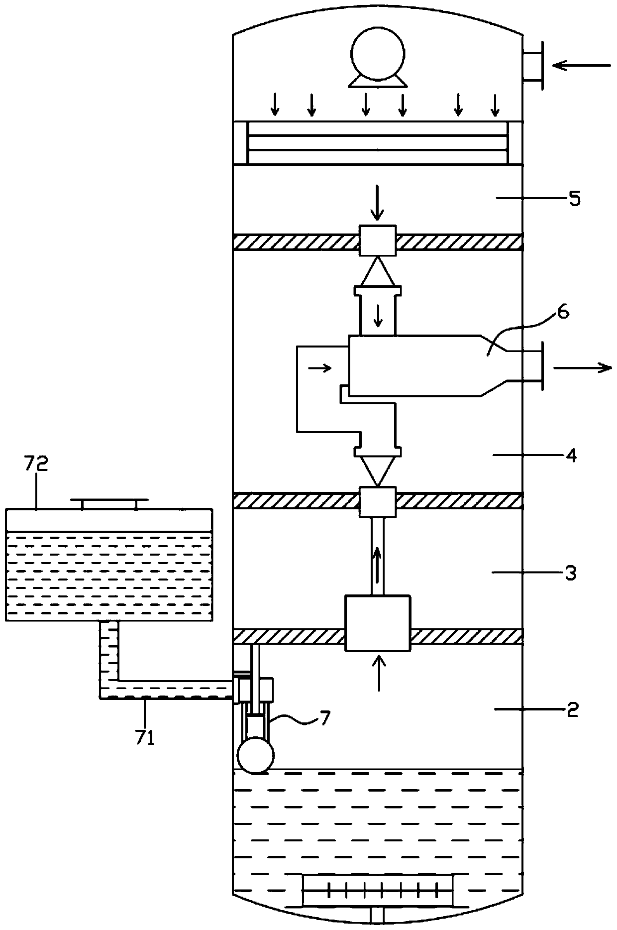
[0053] refer to Figure 3-5 , On the basis of Embodiment 1 or 2, further, the ultrasonic atomization device further includes an automatic liquid replenishment assembly 7, and the automatic liquid replenishment assembly 7 includes a liquid replenishment port 70 arranged on the side of the atomization chamber 2, through which the liquid replenishment pipe 71 and the liquid replenishment The liquid storage tank 72 connected to the port 70, the guide rod 73 fixed on the bottom of the first partition 12, the sealing plug 74 that can slide vertically on the guide rod 73, and the sealing plug 74 fixed on the side of the sealing plug 74 The sealing rubber sheet 75 used to seal the liquid replenishing port 70 and the floating ball 76 fixed to the lower part of the sealing plug 74 through a connecting rod.

[0054] A limit rod 77 is connected between the inner wall of the atomization chamber 2 above the liquid replenishment port 70 and the guide rod 73;

[0055] The middle part of the ...


PUM


Abstract

The invention discloses an ultrasonic atomizing device. The ultrasonic atomizing device comprises an atomizing box, an atomizing chamber, a mist discharging chamber, a mixing chamber, a heating chamber, an ultrasonic transducer, an air pump, a mist discharging spray head, a fan, a heater and an exhaust nozzle, wherein the atomizing chamber, the mist discharging chamber, the mixing chamber and theheating chamber are sequentially arranged in the atomizing box from bottom to top, the ultrasonic transducer is arranged in the atomizing chamber, the air pump is arranged in the mist discharging chamber, the mist discharging spray head is connected with the air pump, the fan and the heater are arranged in the heating chamber, and the exhaust nozzle is used for exhausting hot air in the heating chamber into the mixing chamber. According to the ultrasonic atomizing device, liquid can be atomized into smaller liquid drops through combination of primary ultrasonic and secondary hot air so that the atomized liquid drops can suspend in the air for a long time, and a better use effect is achieved; mist and hot air can be sufficiently mixed by arranging a flow guide mixing assembly, the heating effect of the hot air on the mist can be improved, and droplets with smaller diameters can be formed by the mist; and according to the ultrasonic atomizing device, by arranging an automatic liquid supplementing assembly, solution supplementing can be automatically carried out on the atomizing chamber, so that efficient operation of the ultrasonic atomizing device is maintained.

Description

technical field [0001] The invention relates to the field of medical instruments, in particular to an ultrasonic atomization device. Background technique [0002] Ultrasonic atomization devices have a variety of application functions, for example, they can be used for air humidification, air disinfection and sterilization, or for nebulization inhalation therapy in hospitals, etc. The basic principle is to aerosolize the liquid through an ultrasonic transducer to be discharged into the application. When the current ultrasonic atomization device only atomizes the liquid gas into droplets through the ultrasonic transducer, the diameter of the droplets is often larger, and the droplets with larger diameters are easier to sink in the air, and cannot be suspended more easily. For a long time, the effect of the ultrasonic atomization device will be reduced. For example, when the ultrasonic atomization device is used for disinfection and sterilization, if the atomized droplets of ...

Claims


Application Information

Patent Timeline
Patent Type & Authority Applications(China)
IPC IPC(8): B05B17/06B05B7/04B05B7/16B05B7/26A61L9/14
CPCA61L9/14B05B7/0416B05B7/1606B05B7/262B05B17/06B05B17/0653
Inventor 魏双施段生宝李勇谢劲松王红梅丁少华陈晔洲王玉珏刘杰
Owner SUZHOU INST OF BIOMEDICAL ENG & TECH CHINESE ACADEMY OF SCI
Why Eureka
Try Eureka