Air filter die casting mould for uniform cold forming
A die-casting mold and cold forming technology, which is applied in the field of air filter die-casting molds, can solve the problems of poor crystallization and compactness of castings, easy to produce pores, etc., and achieve the effect of reasonable distribution, good compactness, and favorable cooling and cooling
- Summary
- Abstract
- Description
- Claims
- Application Information
AI Technical Summary
Problems solved by technology
Method used
Image

Examples
Embodiment Construction
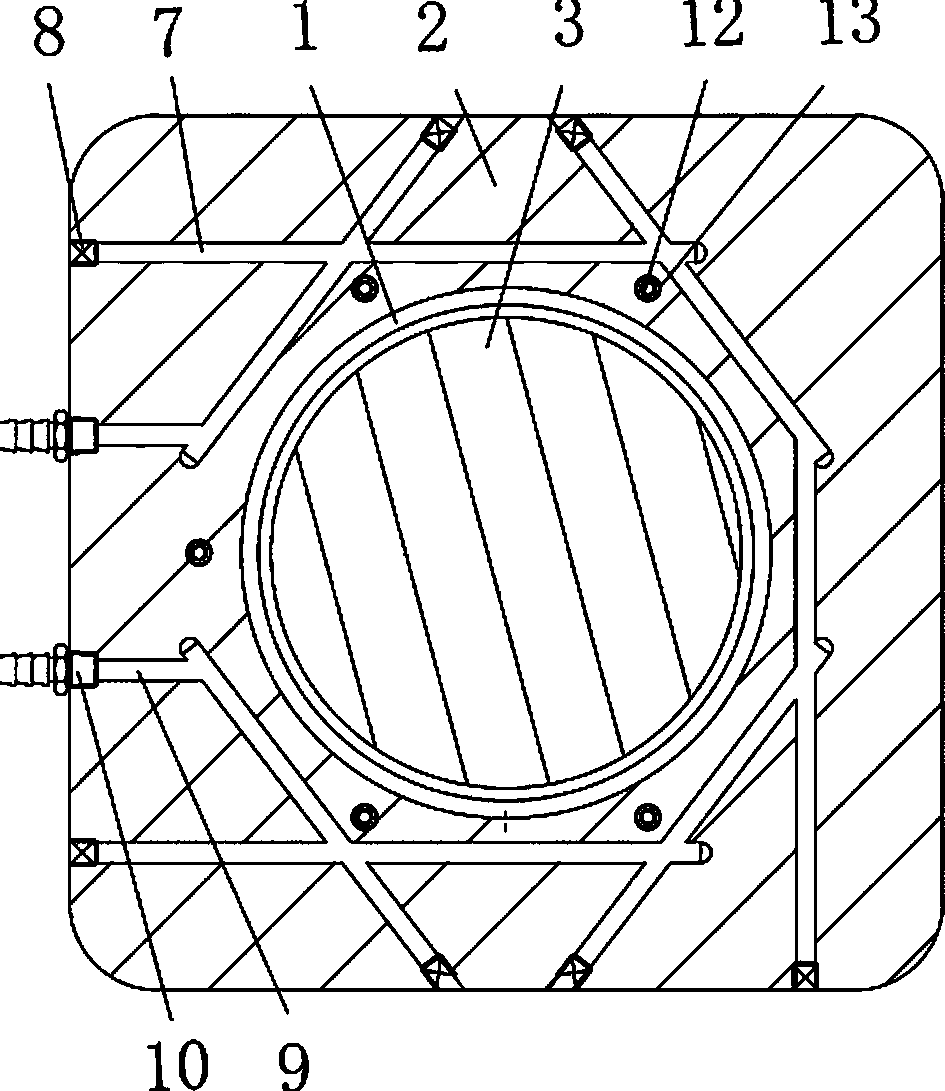
[0012] as attached figure 1 Shown: an air filter die-casting mold for uniform cooling, including: an upper mold 2 with a cavity 1, a lower mold 4 with a core 3, a gating system 5 connected to the cavity 1, and an exhaust channel 6 , the annular cooling assembly and the point cooling assembly located outside the side wall of the cavity 1.
[0013] The annular cooling assembly includes: seven straight cooling channels 7 located in the middle of the outer side of the cavity 1 and connected in sequence, the number of plugs 8 is the same as the number of straight cooling channels 7, two one ends are connected to the side of the upper mold 2 A connecting passage 9 and two connecting joints 10; one end of the straight cooling passage 7 is connected with the side of the upper mold 2; the plug 8 corresponds to the straight cooling passage 7 and blocks one end of the straight cooling passage 7; one connecting The other end of the road 9 communicates with the other end of the first stra...
PUM
 Abstract
Description
Claims
Application Information
 - Generate Ideas
- Intellectual Property
- Life Sciences
- Materials
- Tech Scout
- Unparalleled Data Quality
- Higher Quality Content
- 60% Fewer Hallucinations
Browse by: Latest US Patents, China's latest patents, Technical Efficacy Thesaurus, Application Domain, Technology Topic, Popular Technical Reports.
© 2025 PatSnap. All rights reserved.Legal|Privacy policy|Modern Slavery Act Transparency Statement|Sitemap|About US| Contact US: help@patsnap.com