Multi-state parallel multi-degree-of-freedom motion platform based on piezoelectric driving

A piezoelectric drive and motion platform technology, applied in the field of mechanics, can solve the problems that the platform cannot simultaneously have a large travel range, high positioning accuracy and high dynamic response, and cannot apply a large range of precision tracking, etc., and achieves excellent vibration attenuation performance. Lightweight and compact effect

Active Publication Date: 2020-06-02
INST OF OPTICS & ELECTRONICS - CHINESE ACAD OF SCI
View PDF11 Cites 1 Cited by
  • Summary
  • Abstract
  • Description
  • Claims
  • Application Information

AI Technical Summary

Problems solved by technology

There are many actuation methods for the six-degree-of-freedom parallel platform, such as linear motor drive, ball screw drive, voice coil motor and piezoelectric material actuator, etc., but due to the limitation of the six-degree-of-freedom par

Method used


Image

  • Multi-state parallel multi-degree-of-freedom motion platform based on piezoelectric driving
  • Multi-state parallel multi-degree-of-freedom motion platform based on piezoelectric driving
  • Multi-state parallel multi-degree-of-freedom motion platform based on piezoelectric driving

Examples


Embodiment example 1

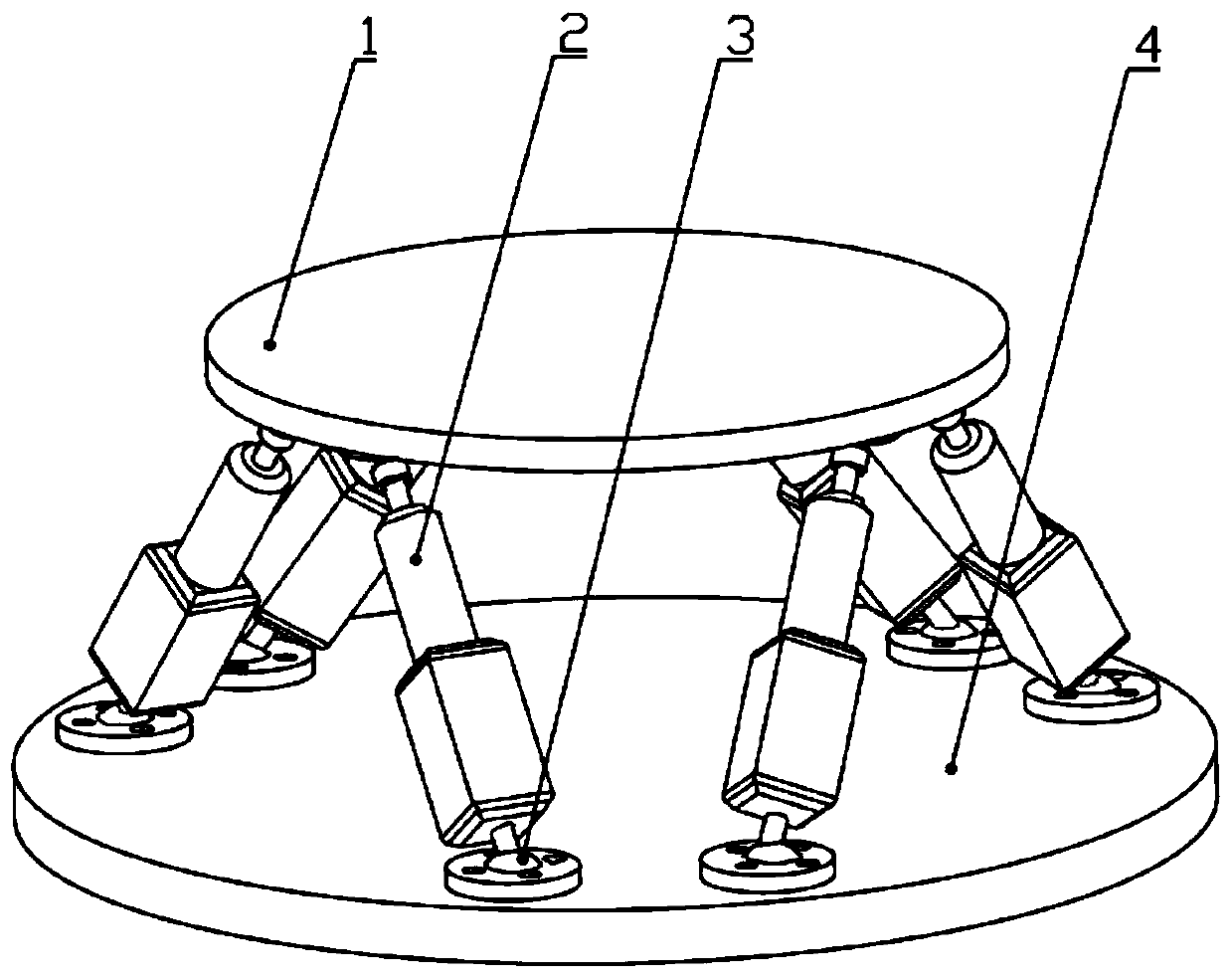
[0018] See attached Figure 1-3 , a multi-state parallel multi-degree-of-freedom motion platform based on piezoelectric drive of the present invention includes:

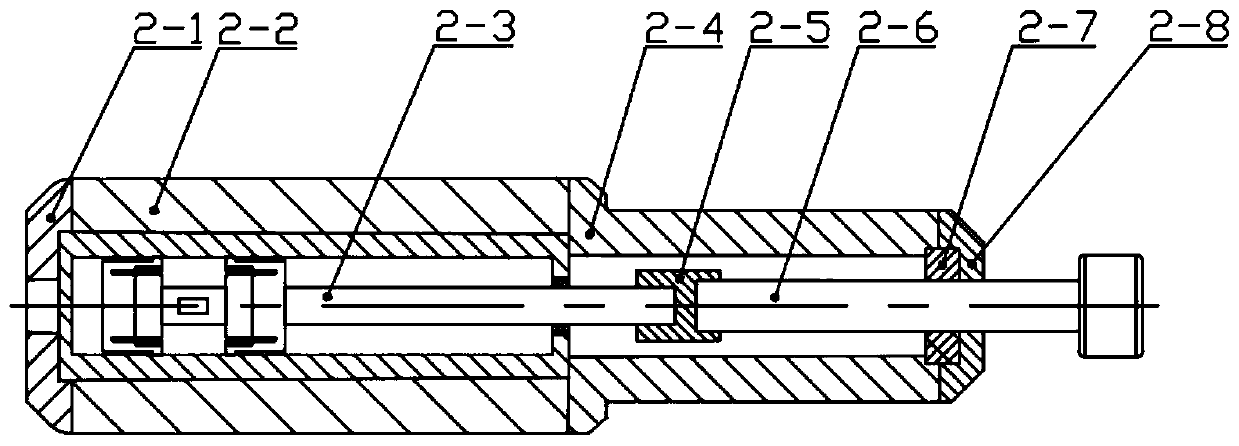
[0019] A static platform 4; a dynamic platform 1 arranged coaxially and parallel to the static platform 4; six linear drive assemblies 2 arranged between the static platform 4 and the dynamic platform 1, and each linear drive assembly 2 ends through a spherical bearing 3 They are respectively connected to the lower end surface of the moving platform 1 and the upper end surface of the static platform 4; the linear drive assembly 2 includes an end cover 2-1, an actuator protective case 2-2, a piezoelectric inchworm actuator 2-3, and an output shaft Housing 2-4, coupling 2-5, output shaft 2-6, bearing 2-7, bearing end cover 2-8, the position of the piezoelectric inchworm actuator 2-3 is determined by the end cover 2-1 It is fixed with the output shaft shell 2-4, the actuator actuating shaft 2-3-8 is connected with the ...

Embodiment approach

[0022] As a preferred embodiment of the present invention, specifically as follows:

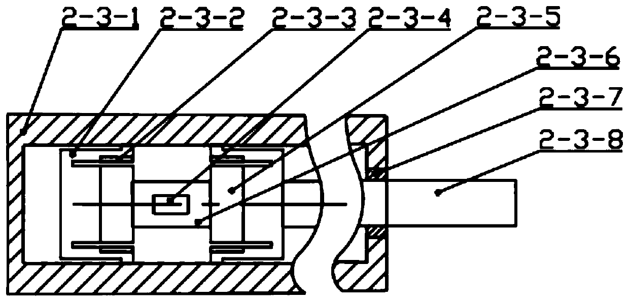
[0023] In the first step, the electromagnet 2-3-5 of the second clamping mechanism is energized, and the magnetic force is applied to attract the armature 2-3-3, and the armature drives the flexible part 2-3-2 to separate from the track 2-3-1. The second clamping mechanism releases the clamping state;

[0024] In the second step, the extension piezoelectric stack 2-3-6 is energized and extended, and the displacement is output, and the actuating shaft 2-3-8 is moved outward by one step;

[0025] In the third step, after the elongation of the piezoelectric stack 2-3-6 is complete, the second clamping electromagnet 2-3-5 is powered off and loses its magnetic force, and the armature 2-3-3 and the flexible part 2-3-2 recover In the original position, the second clamping mechanism resumes clamping;

[0026] In the fourth step, the first clamping electromagnet 2-3-5 is energized to attract the arm...

Embodiment example 2

[0030] The difference between this implementation case and implementation case 1 lies in the movement form of the actuator, as follows:

[0031] The first clamping mechanism is always in the clamping state, and the second clamping mechanism is always in the unclamping state. At this time, the actuator is in the scanning state, also known as the linear state. Whether the extension piezoelectric stack 2-3-6 is powered is determined by the outside The controller decides that at this time, the displacement of the actuator is small, the response is fast, and the precision is high, which can realize the vibration isolation positioning function of the multi-degree-of-freedom parallel motion platform.


PUM


Abstract

The invention discloses a multi-state parallel multi-degree-of-freedom motion platform based on piezoelectric driving, and belongs to the technical field of motion mechanics. The multi-state parallelmulti-degree-of-freedom motion platform based on piezoelectric driving has two motion states of stepping and scanning. The multi-state parallel multi-degree-of-freedom motion platform based on piezoelectric driving comprises a static platform, a moving platform placed coaxially parallel to the static platform and six linear driving assemblies disposed between the static platform and the moving platform, and two ends of each linear driving assembly are connected with the lower end surface of the moving platform and the upper end surface of the static platform through spherical bearings; the linear driving assemblies comprises end covers, actuator protective shells, piezoelectric inchworm-type actuators, couplings, bearings, output shafts, output shaft shells and bearing end covers. The piezoelectric inchworm-type actuators comprise tracks, flexible members, armatures, electromagnets, elongated piezoelectric stacks, strain gauges, axle sleeves and actuating shafts. Clamping mechanisms comprise electromagnets, armatures and flexible members. The strain gauges are pasted on the elongated piezoelectric stacks, one ends of the actuating shafts are fixed to the back of one of the clampingmechanisms, and the other ends of the actuating shafts are supported by the axle sleeves.

Description

technical field [0001] The invention belongs to the technical field of mechanisms, and in particular relates to a multi-state parallel multi-degree-of-freedom motion platform based on piezoelectric drive. Background technique [0002] In recent years, realizing accurate and stable tracking of precision optical equipment has become a research hotspot in the field of aerospace. The six-degree-of-freedom parallel platform has the characteristics of good vibration control effect, high pointing control accuracy, strong fault tolerance, stable and compact structure, and large bearing capacity. It is widely used in vibration isolation and space pointing tracking. There are many actuation methods for the six-degree-of-freedom parallel platform, such as linear motor drive, ball screw drive, voice coil motor and piezoelectric material actuator, etc., but due to the limitation of the six-degree-of-freedom parallel platform actuator type, the This type of platform cannot have the perfo...

Claims


Application Information

Patent Timeline
IPC IPC(8): B25J9/00
CPCB25J9/0057
Inventor 亓波李含敬子建任戈彭起
Owner INST OF OPTICS & ELECTRONICS - CHINESE ACAD OF SCI
Why Eureka
Try Eureka