Hall thruster with novel buffer cavity

A technology of Hall thruster and buffer cavity, which is applied in the direction of thrust reverser, machine/engine, and utilization of plasma, which can solve the problems of low gas density and homogenization degree, and achieve the problem of alleviating the problem of gas unevenness and high magnetic energy. The effect of accumulation and homogenization is sufficient

Active Publication Date: 2020-06-02
HARBIN INST OF TECH
View PDF13 Cites 9 Cited by
  • Summary
  • Abstract
  • Description
  • Claims
  • Application Information

AI Technical Summary

Problems solved by technology

[0005] In order to solve the problem of low gas density and low homogenization degree of the existing low-power Hall thruster due to too small size, the present invention provides a Hall thruster with a new type of buffer cavity, and uses the new type of buffer cavity to improve the low power The degree of homogenization and density of the neutral gas of the Hall thruster improves the discharge performance and stability of the Hall thruster

Method used


Image

  • Hall thruster with novel buffer cavity
  • Hall thruster with novel buffer cavity

Examples


Embodiment approach

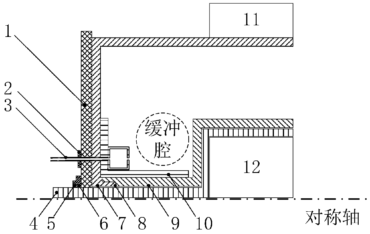
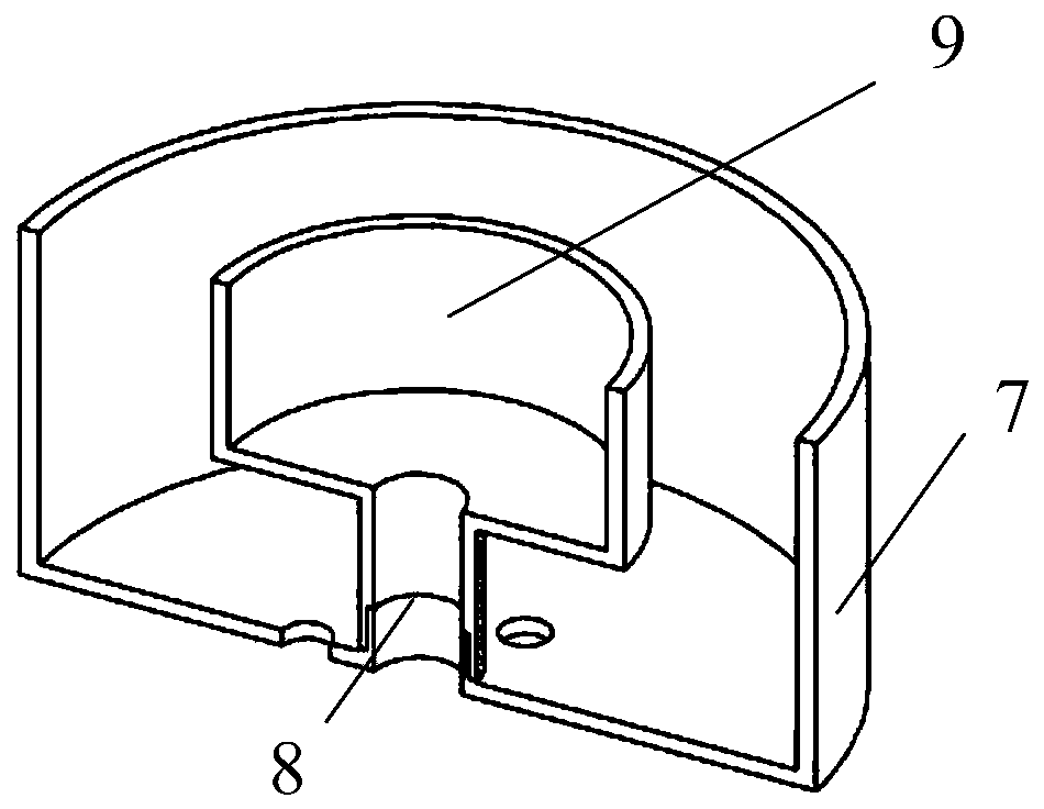
[0018] combined with Figure 1 to Figure 2 Describe the specific embodiment of the present invention: the present invention is a Hall thruster with a novel buffer cavity, such as figure 1 As shown, it includes bottom plate 1, nut 2, gas distributor 3, permanent magnet support 4, fixing nut 5, outer ceramic screen 7, inner ceramic screen 9, anode 10, outer permanent magnet 11 and inner permanent magnet 12; outer ceramic screen 7 and the inner ceramic screen 9 are cylindrical structures nested inside and outside, and there are radial gaps and axial gaps between the outer ceramic screen 7 and the inner ceramic screen 9, forming a buffer cavity between the outer ceramic screen 7 and the inner ceramic screen 9. Structure; the anode 10 and the inner ceramic screen 9 are fixedly installed on the base plate 1 through the gas distributor 3 and the nut 2; the inner permanent magnet 12 is fixedly installed in the outer ceramic screen 7 through the permanent magnet bracket 4, and the fixi...


PUM


Abstract

The invention discloses a Hall thruster with a novel buffer cavity, and belongs to the technical field of Hall thrusters. The Hall thruster with the novel buffer cavity solves the problems that in thecase of an existing low-power Hall thruster, due to the fact that the size is too small, gas density and homogenization degree are not high. An inner ceramic screen and an outer ceramic screen of theHall thruster with the novel buffer cavity are of an inside-and-outside nested cylindrical structure, a radial gap and an axial gap are formed between the inner ceramic screen and the outer ceramic screen, so that a buffer cavity structure between the inner ceramic screen and the outer ceramic screen is formed, an anode and the outer ceramic screen are fixedly mounted on a bottom plate through agas distributor and a nut, an inner permanent magnet is fixedly mounted in the inner ceramic screen through a permanent magnet support, and is fixedly mounted on the bottom plate through a fixing nut,and an outer permanent magnet is mounted on the outer side of the outer ceramic screen in a sleeving mode. A discharge channel of the Hall thruster with the novel buffer cavity is formed by insertingthe outer ceramic screen and the inner ceramic screen, the buffer cavity is formed at the area between the outer ceramic screen and the inner ceramic screen, a gas motion path is enlarged through thenovel buffer cavity structure, and gas is more sufficiently homogenized.

Description

technical field [0001] The invention relates to a Hall thruster with a novel buffer cavity, belonging to the technical field of Hall thrusters. Background technique [0002] Hall thrusters are currently widely used in electric propulsion systems. Compared with traditional chemical propulsion, they have the advantages of high efficiency, high specific impulse, high thrust density, high efficiency and long life. Its working principle is: there is an orthogonal electromagnetic field in the discharge channel of the Hall thruster, and the electrons emitted from the cathode into the channel are affected by the orthogonal electromagnetic field and drift to the anode, and at the same time, the working fluid ejected from the gas distributor The gas is ionized by collision, and the ionized electrons are confined in the channel by the radial magnetic field due to their small mass. However, the ion mass is large and the magnetic field cannot constrain it, so it is accelerated and ejecte...

Claims


Application Information

Patent Timeline
IPC IPC(8): F03H1/00
CPCF03H1/0087
Inventor 丁永杰李鸿魏立秋于达仁
Owner HARBIN INST OF TECH
Why Eureka
Try Eureka