
Conductive backboard with high heat dissipation and low resistivity and manufacturing method thereof

A low-resistivity, conductive backplane technology, applied in the field of solar cells, to achieve the effect of improving outdoor weather resistance, prolonging service life, and improving use stability

Inactive Publication Date: 2020-06-02
SUZHOU CHENGBANG DALI MATERIAL TECH
View PDF1 Cites 0 Cited by
  • Summary
  • Abstract
  • Description
  • Claims
  • Application Information

AI Technical Summary

Problems solved by technology

[0005] In view of this, the present invention provides a high heat dissipation and low resistivity conductive backplane and its manufacturing method, which can solve the problems of existing solar photovoltaic backplanes

Method used


Image

  • Conductive backboard with high heat dissipation and low resistivity and manufacturing method thereof

Examples


Embodiment 1

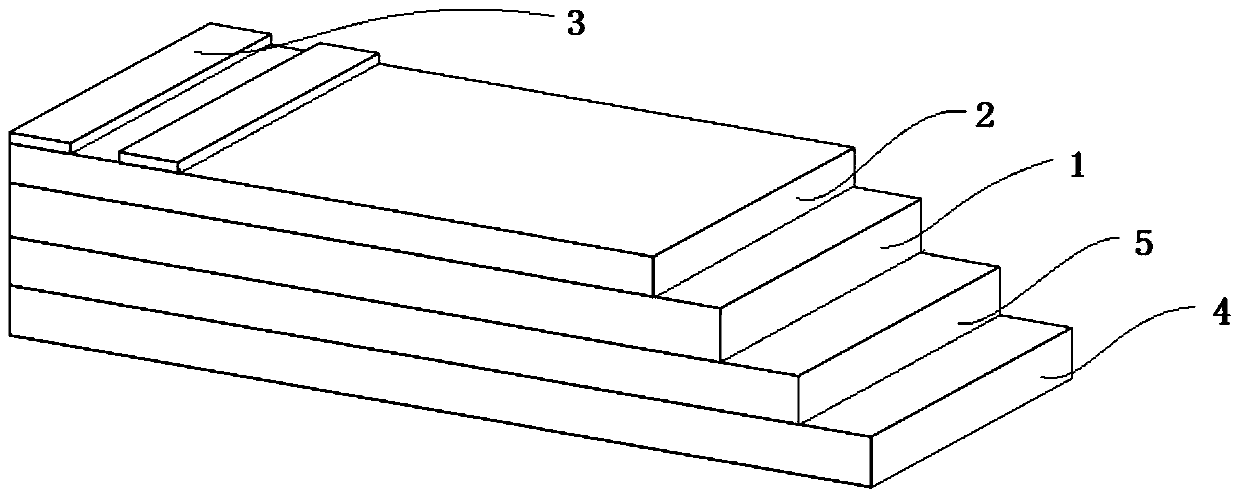
[0033] A conductive backplane with high heat dissipation and low resistivity and its manufacturing method, comprising: a carrier substrate layer 1, a thermally conductive adhesive layer 2, a metal layer 3, a weather-resistant layer 4, and a weather-resistant adhesive layer 5;

[0034] Concrete preparation process is as follows:

[0035] step 1

[0036] Preferably, the metal layer 3 is copper foil with a thickness of 10 μm.

[0037] The carrier substrate layer 1 is preferably modified polyethylene terephthalate (PET), which is rectangular and has a thickness of 20 μm. The raw material of the thermally conductive adhesive layer 2 is evenly coated on its upper surface, which includes: polyurethane adhesive agent, modified phenolic resin, and 2% aluminum oxide by mass percentage, and form a thermally conductive adhesive layer 2 with a thickness of 5 μm, and then attach the lower surface of the metal layer 3 (copper foil) to the thermally conductive adhesive layer 2, on the upper ...

Embodiment 2

[0045] A conductive backplane with high heat dissipation and low resistivity and its manufacturing method, comprising: a carrier substrate layer 1, a thermally conductive adhesive layer 2, a metal layer 3, a weather-resistant layer 4, and a weather-resistant adhesive layer 5;

[0046] Concrete preparation process is as follows:

[0047] step 1

[0048] Preferably, the metal layer 3 is copper foil with a thickness of 50 μm.

[0049]The carrier substrate layer 1 is preferably modified polyethylene terephthalate (PET), which is rectangular and has a thickness of 250 μm. The raw material of the thermally conductive adhesive layer 2 is evenly coated on its upper surface, which includes: two-component polyurethane Adhesive, modified phenolic resin, and 30% aluminum oxide by mass percentage, and form a thermally conductive adhesive layer 2 with a thickness of 30 μm, and then attach the lower surface of the metal layer 3 (copper foil) to the thermally conductive adhesive layer 2, Pr...


PUM

PropertyMeasurementUnit
Thicknessaaaaaaaaaa
Thicknessaaaaaaaaaa
Thicknessaaaaaaaaaa

Abstract

The invention discloses a conductive backboard with high heat dissipation and low resistivity and a manufacturing method thereof. The method comprises the steps of uniformly coating a carrier base material layer with a raw material of a heat-conduction bonding layer, compounding a metal layer, and carrying out the curing; further processing an upper conductive circuit on the exposed surface of themetal layer of the product through exposure, development and etching; and finally, coating a weather-proof layer with a raw material of a weather-proof bonding layer, and compounding the weather-proof layer on the unprocessed surface of the processed carrier base material layer to form the conductive backboard provided by the invention. The scheme of the invention has the advantages that the weather resistance of the conductive backboard is improved through the designed multi-layer structure, and the solar conversion efficiency and the heat dissipation performance of the backboard are improved through improving the raw materials.

Description

technical field [0001] The invention relates to the field of solar cells, in particular to a conductive backplane and a manufacturing method thereof. Background technique [0002] The solar photovoltaic industry is a strategic and leading green industry in the world. For solar cells, the conversion efficiency is an important parameter. At present, the conversion rate of silicon-based batteries is between 10% and 30%, and the rest of the solar energy will be converted into other energy forms and lost, of which heat energy accounts for the vast majority. Therefore, continuously improving the conversion rate of photovoltaic modules is the key to reducing the cost of power generation. At the same time, it is also necessary to reduce the adverse effects of the modules due to the absorption and accumulation of heat converted from solar energy. At present, in order to improve the photoelectric conversion efficiency of the module as much as possible, various methods are used in the...

Claims


Application Information

Patent Timeline
IPC IPC(8): H01L31/049H01L31/052H01L31/18
CPCH01L31/049H01L31/052H01L31/18Y02E10/50
Inventor 闫勇张丽萍
Owner SUZHOU CHENGBANG DALI MATERIAL TECH
Learn More