
Eureka
For R&D, Eureka makes reading and utilizing patents & technical documents easy.
Eureka AIR
Designed for self-driven R&D workflows. Generate viable solutions, solve complex R&D challenges, empower your innovation with AI.

Eureka Materials
Designed for material experts only. Revolutionize your material R&D, from search, analyze, to developing new materials.

TechResearch
Generate reliable direction feasibility study reports for your R&D in just a few steps.

TechSeek
Discover and master advanced knowledge NOW. Basics, ideas, possibilities, all at once.

TechMind
As an expert in R&D Theories, TechMind can generates customized viable solutions instantly.

TechRisk
Analyze your overall solution with one click, know your potential R&D risks in advance.

TechMonitor
Get weekly tech updates, stay abreast of the latest tech innovations and key insights.
Copper mine wasteland soil heavy metal pollution remediation device
A technology for pollution remediation and heavy metals, which is applied in the field of soil remediation, can solve the problems of poor removal of heavy metals in the soil, single structure, and failure to repair the soil, etc., to achieve the effect of improving the removal effect of heavy metals and better repairing the soil
- Summary
- Abstract
- Description
- Claims
- Application Information
AI Technical Summary
Problems solved by technology
Method used
Image

Examples
Embodiment 1
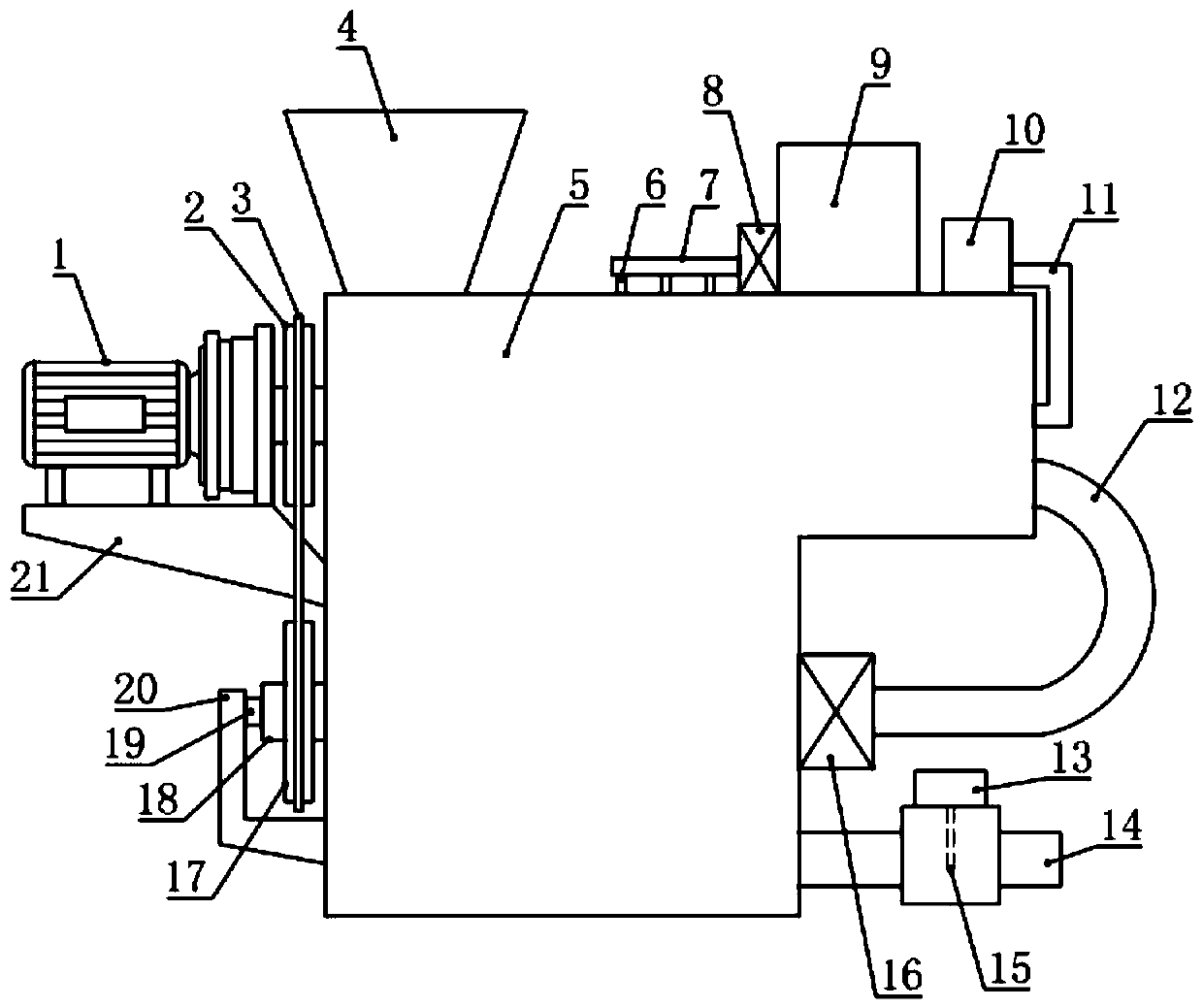
[0018] see Figure 1-2 , in the embodiment of the present invention, a copper ore abandoned land soil heavy metal pollution remediation device includes a body 5, the upper and lower parts of the body 5 are respectively provided with an upper chamber 26 and a lower chamber 28, and the upper chamber 26 and the lower chamber 28 are respectively equipped with a conveying and breaking up assembly and a stirring electrolysis assembly, and the conveying and breaking up assembly and the stirring electrolysis assembly are driven by a drive mechanism installed on the body 5, and the upper chamber 26 is also driven by a U-shaped The conveying pipe 12 communicates with the lower chamber 28, and is used for conveying mud through the U-shaped conveying pipe 12. The body 5 is also equipped with an infusion device and an exposure device for replenishing liquid and conveying compressed air to the middle of the upper chamber 26. gas device.
[0019] In the embodiment of the present invention, ...
Embodiment 2
[0021] see Figure 1-4 , the difference between this embodiment and embodiment 1 is:
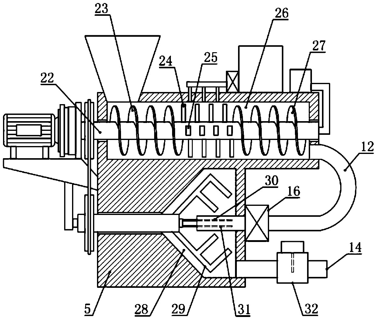
[0022] In this example, if figure 2 As shown, the upper chamber 26 is a horizontally arranged cylindrical structure, and the conveying and breaking assembly includes a rotating tube 22, a first screw blade 23, a breaking rod 24 and a second screw blade 27, and the rotating tube 22 Axially installed in the middle part of the upper chamber 26, and the two ends of the rotating tube 22 are in sealing and rotating connection with the body 5, and some breaking rods 24 are installed on the rotating tube 22 in the middle part of the upper chamber 26. The first helical blade 23 and the second helical blade 27 for conveying the soil to the right are respectively installed on the rotating pipe 22 on the side, and the first helical blade 23 and the second helical blade 27 have a better squeezing and conveying effect on the soil , Breaking up the rod 24 has a better effect of breaking up the soil.
...
PUM
 Abstract
Description
Claims
Application Information
 - R&D Engineer
- R&D Manager
- IP Professional
- Industry Leading Data Capabilities
- Powerful AI technology
- Patent DNA Extraction
Browse by: Latest US Patents, China's latest patents, Technical Efficacy Thesaurus, Application Domain, Technology Topic, Popular Technical Reports.
© 2024 PatSnap. All rights reserved.Legal|Privacy policy|Modern Slavery Act Transparency Statement|Sitemap|About US| Contact US: help@patsnap.com