A centrifugal separation device for river sludge treatment process

A technology for sludge treatment and centrifugal separation, applied in sludge treatment, water/sludge/sewage treatment, centrifuges with rotating drums, etc. and other problems, to achieve the effect of improving service life, sufficient dehydration, and high cleaning efficiency

Active Publication Date: 2020-12-04
乐清市路航电气有限公司
View PDF9 Cites 0 Cited by
  • Summary
  • Abstract
  • Description
  • Claims
  • Application Information

AI Technical Summary

Problems solved by technology

[0003] In the existing sludge centrifugal separation device, because the sludge is fed slowly through the external thrust, a large amount of sludge is easily deposited on the pipe wall during the contact and friction process between the mud and the pipe wall. When cleaning, it needs to be manually scraped into the mud inlet pipe. The cleaning method is very troublesome; at the same time, dirt will also be deposited on the inner wall of the drum of the centrifugal separation device. Because there is a mud screw inside, the shell needs to be opened for cleaning, or there are multiple one-way spray holes built into the inner wall, which will damage the device. Wholeness

Method used


Image

  • A centrifugal separation device for river sludge treatment process
  • A centrifugal separation device for river sludge treatment process
  • A centrifugal separation device for river sludge treatment process

Examples


Embodiment

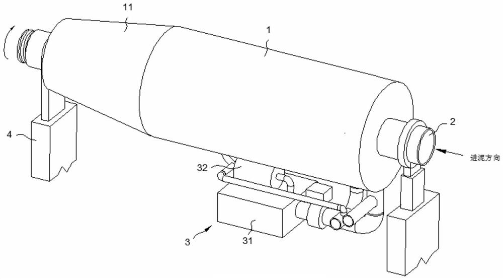
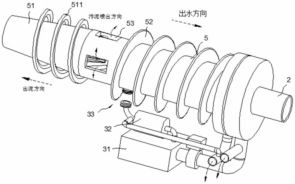
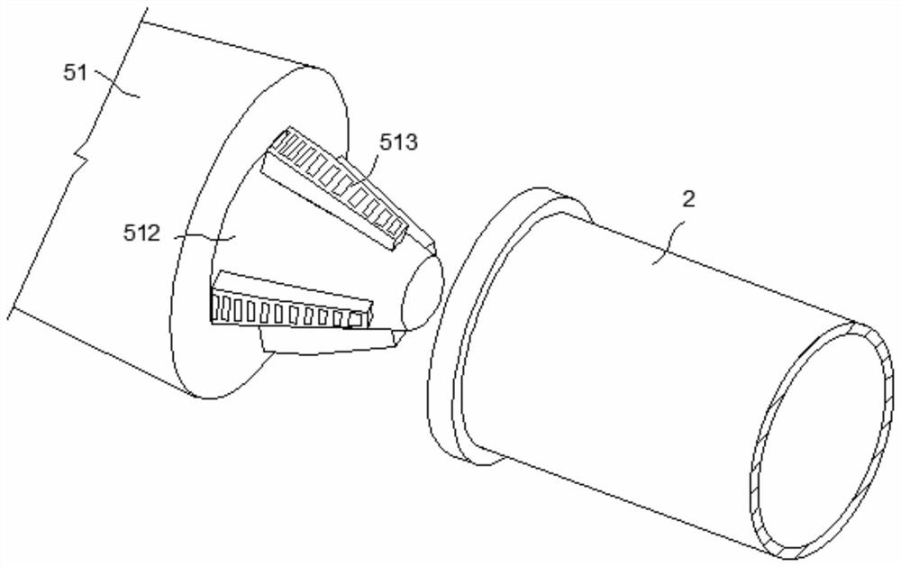
[0034] Embodiment: When using the centrifugal separation device, when working, the external torque drives the mud inlet pipe 2 and the drum 5 to rotate, and due to the centrifugal force, the sludge discharged from the mud inlet pipe 2 is sent into the drum 5 , the differential clutch is used to make the mud inlet pipe 2 and the drum 5 have a speed difference, increase the exit speed of the mud in the mud inlet pipe 2, so that the mud can be thrown into the shell 1; when the rectifier cone 512 works normally, it is fixed at the second On the second tapered part 51, the mud coming in from the mud inlet pipe 2 is dispersed by the rectifying cone 512 and then rotated by the scraper 513 and thrown out of the mud hole 53 to spread out to better separate the mud and water. During normal operation, the rectifying cone is used to The sludge is diverted to make it convenient to switch between the two functions; when cleaning the mud, first start the first motor 55, and its output shaft d...


PUM


Abstract

The invention discloses a centrifugal separation device for river sludge treatment process, which comprises a casing, a mud inlet pipe, a fixing seat and a rotating drum, one end of the casing is a first tapered part, and the two ends of the casing are connected to The fixed seat is fixed by welding, and a drum is movably connected between the two fixed seats through bearings, and one end of the drum is connected to the external torque, and the drum is a hollow structure, and one end of the drum is a second tapered The first tapered part and the second tapered part are arranged in the same vertical plane, and a mud inlet pipe is arranged inside the drum, and a differential clutch is connected between the mud inlet pipe and one end of the drum , a rectifying cone is installed at one end of the second tapered part, and a scraper is evenly arranged on the outside of the rectifying cone, and the rotating outer diameter of the scraper is equal to the inner diameter of the mud inlet pipe, and the rectifying cone is attached to the second cone The side wall of the shape part, according to the present invention, has the characteristics of easy cleaning and removal of internal dirt.

Description

technical field [0001] The invention relates to the technical field of sludge treatment, in particular to a centrifugal separation device used in a river sludge treatment process. Background technique [0002] The sludge in the refinery sewage treatment plant is composed of oil sludge, scum and residual activated sludge, which is usually called "three sludges". Sludge includes dirty oil. The centrifugal dehydrator is a traditional sludge treatment equipment that uses the centrifugal force generated by the high-speed rotation of the drum for solid-liquid separation. [0003] In the existing sludge centrifugal separation device, because the sludge is fed slowly through the external thrust, a large amount of sludge is easily deposited on the pipe wall during the contact and friction process between the mud and the pipe wall. When cleaning, it needs to be manually scraped into the mud inlet pipe. The cleaning method is very troublesome; at the same time, dirt will also be depo...

Claims


Application Information

Patent Timeline
Patent Type & Authority Patents(China)
IPC IPC(8): C02F11/127B04B1/20B04B7/08B04B15/06B04B9/02B04B7/16
CPCC02F11/127
Inventor 奚文婷
Owner 乐清市路航电气有限公司
Why Eureka
Try Eureka