Drilling fluid leakage prediction method for fissured formation

A prediction method and drilling fluid technology, applied in the directions of measurement, earthwork drilling, wellbore/well components, etc., can solve the problems of lack of scientific basis and inability to take leak prevention and plugging measures

Active Publication Date: 2020-06-05
CHINA UNIV OF PETROLEUM (EAST CHINA)
View PDF5 Cites 6 Cited by
  • Summary
  • Abstract
  • Description
  • Claims
  • Application Information

AI Technical Summary

Problems solved by technology

What measures to take after drilling fluid loss in fractured formations mainly depends on the experience and judgment of operators, lacks scientific basis, and cannot take reasonable leak prevention and plugging measures to remedy, so the existing prediction technology for drilling fluid loss in fractured formations There is no one that can be detected in time and accurately and quantitatively predicted, so that field engineers can adopt reasonable and efficient plugging technology in time according to the formation leakage situation, solve drilling risks in time, and reduce drilling fluid loss

Method used


Image

  • Drilling fluid leakage prediction method for fissured formation
  • Drilling fluid leakage prediction method for fissured formation
  • Drilling fluid leakage prediction method for fissured formation

Examples


Embodiment 1

[0083] A method for predicting drilling fluid loss in fractured formations, comprising the following steps:

[0084] A method for predicting drilling fluid loss in fractured formations, comprising the following steps:

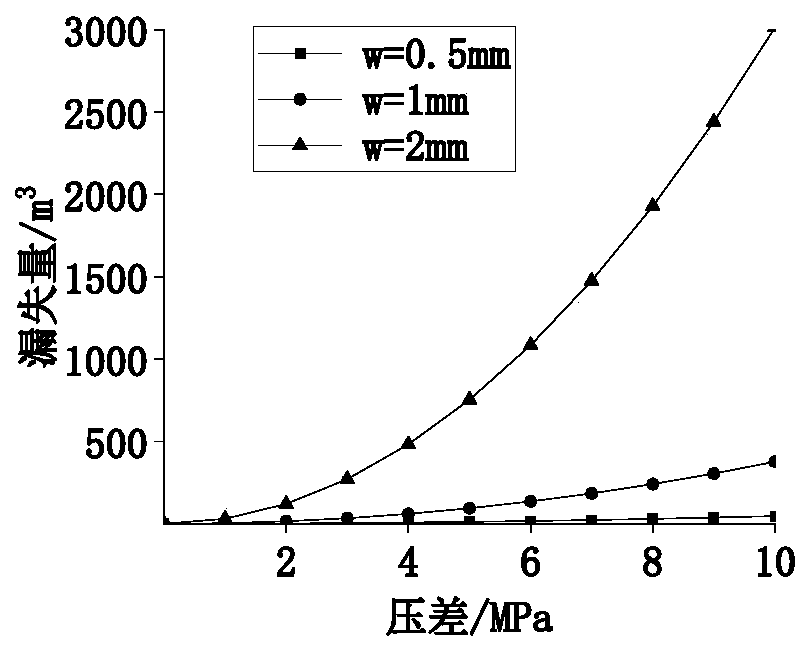
[0085] A. Calculate the width w of various fractures through electrical imaging logging data;

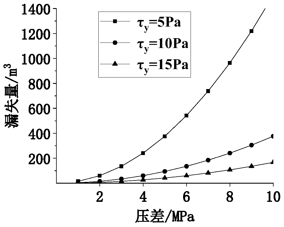
[0086] B. Measure the viscosity coefficient k, flow property index m and yield stress τ of the drilling fluid with a rotational viscometer y ;

[0087] C. Calculate formation pressure p p , specifically, the formation pressure p p ;Select the shale section with shale content greater than 80% on the standard acoustic time difference data, read out the corresponding acoustic time difference value of the well depth at intervals of 5m, and draw points on the semi-logarithmic curve; establish a normal compaction trend line and the normal compaction trend line equation; bring the acoustic time difference on the logging curve into the trend line equation to obtain the e...

Embodiment 2

[0153] A method for predicting the leakage of drilling fluid in fractured formations, the steps are as shown in Example 1, and the parameters required for predicting the leakage of drilling fluid in fractured formations are shown in Table 1

[0154] Table 1: Parameters required to calculate leakage

[0155] parameter parameter value w 0.5mm r w

0.03m r i

1m τ y

10pa·s k 0.1pa·s m

m 0.8 Q 0.1m 3 / s

p w

30MPa P p

20MPa δ 1.8 V lost

235.30m 3

Field practice 221.02m 3

error 6.46%

[0156] Given the parameters in Table 1, the total loss of drilling fluid is calculated according to formula (23), which is 235.30m 3 , the total leakage measured on site is 221.02m 3 , the error is 6.46%, indicating that the drilling fluid loss prediction method of the present invention is not much different from the actual one, and can quantitatively predict the drilling fluid lo...


PUM


Abstract

The invention relates to a drilling liquid leakage prediction method for fissured formation, and belongs to the field of petroleum and natural gas drilling engineering. The method comprises the following steps that A, the width w of various fissures is calculated; B, the consistency coefficient k of a drilling fluid, the flow behavior index m and the drilling fluid yield stress tau<y> are measured; C, the formation pressure p is calculated; and D, the leakage of the drilling fluid is calculated according to a formula, a drilling fluid leakage model is obtained though the following method that the drilling fluid mass conservation equation, the leakage momentum equation, the rheological equation of a fluid and the tortuosity equation are solved simultaneously to obtain a formula (18) anda formula (23), the formula (18) is the relationship between the differential pressure and the leakage radius, and the formula (23) is the total leakage relationship of the drilling fluid. According to the drilling fluid leakage prediction method for the fissured formation, the leakage of the drilling fluid of the fissured formation can be predicted, so that a field engineer adopts a reasonable and efficient leakage stopping technology in time according to the loss condition of the formation, solves the drilling risk in time, and reduces the loss of the drilling fluid.

Description

technical field [0001] The invention relates to a method for predicting the leakage amount of drilling fluid in a fractured formation, belonging to the field of oil and natural gas drilling engineering. Background technique [0002] Lost circulation is one of the most common downhole complex accidents during drilling in fractured formations. Leakage will not only prolong the well construction period, but also lose a lot of manpower and material resources. If it is not handled properly, it will also induce major accidents such as well collapse and blowout. Three necessary conditions must be met for leakage to occur: (1) there are leakage channels in the formation that cause leakage; (2) the pore size of the leakage channels should be larger than the solid particle content of the drilling fluid; (3) the bottom hole pressure is greater than the formation pore pressure. [0003] At present, there have been some studies on the prediction of drilling fluid loss in fractured form...

Claims


Application Information

Patent Timeline
IPC IPC(8): E21B47/10G06F17/13
CPCE21B47/10G06F17/13
Inventor 白英睿孙金声吕开河雷少飞王金堂黄贤斌刘敬平金家锋
Owner CHINA UNIV OF PETROLEUM (EAST CHINA)
Why Eureka
Try Eureka