Radiographic image detector

A radiographic image and detector technology, applied in the field of detectors, can solve the problems of increase, narrowing of dynamic range, dark current shot noise, etc.

Active Publication Date: 2020-06-05
SHANGHAI IRAY TECH
View PDF6 Cites 3 Cited by
  • Summary
  • Abstract
  • Description
  • Claims
  • Application Information

AI Technical Summary

Problems solved by technology

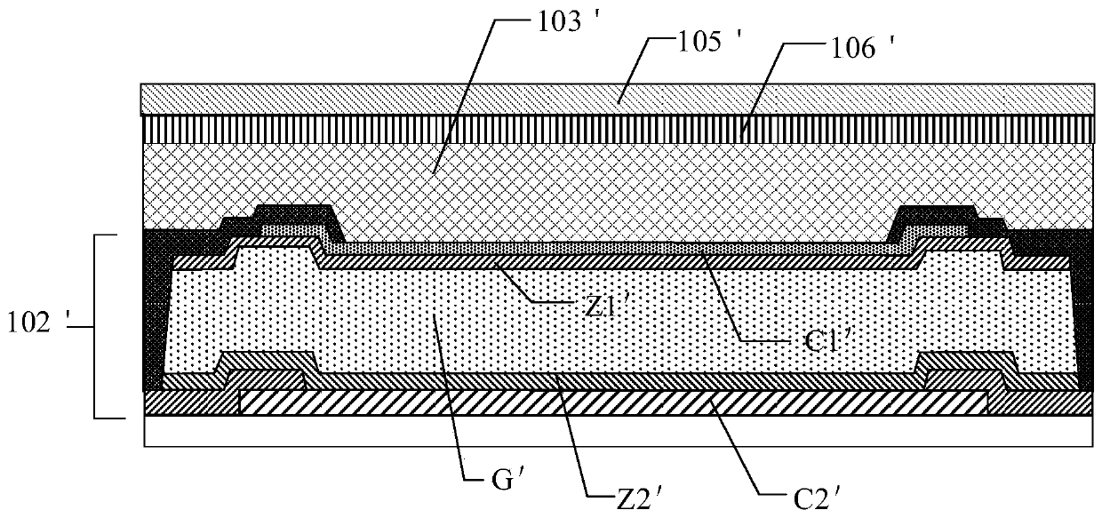
However, the dark current of a semiconductor photodiode is mainly the dark current injected from the cathode or anode (the first electrode C1' or the second electrode C2' in the figure), and it will increase rapidly as the bias voltage increases.
The dark current of the photodiode not only narrows the actual dynamic range of the incident light response, but also causes the shot noise of the dark current and the non-uniformity of the dark current across the entire image detector plane. fake image background
[0004] Dark current and photocurrent are proportional to the area of ​​the photodiode under normal circumstances, so it is impossible to reduce the dark current by simply reducing the area of ​​the photodiode without damaging the photoelectric conversion efficiency of the photodiode

Method used


Image

  • Radiographic image detector
  • Radiographic image detector
  • Radiographic image detector

Examples


Embodiment Construction

[0036] In order to make the purpose, technical solutions and advantages of the embodiments of the present invention clearer, the technical solutions in the embodiments of the present invention will be clearly and completely described below in conjunction with the drawings in the embodiments of the present invention. Obviously, the described embodiments It is a part of embodiments of the present invention, but not all embodiments. All other structures and embodiments obtained by those skilled in the art based on the embodiments and the concepts and methods disclosed in the present invention belong to the protection scope of the present invention.

[0037] Terms used in the embodiments of the present invention are only for the purpose of describing specific embodiments, and are not intended to limit the present invention. As used in the embodiments of the present invention and the appended claims, the singular forms "a", "said" and "the" are also intended to include the plural f...


PUM

PropertyMeasurementUnit
refractive indexaaaaaaaaaa

Abstract

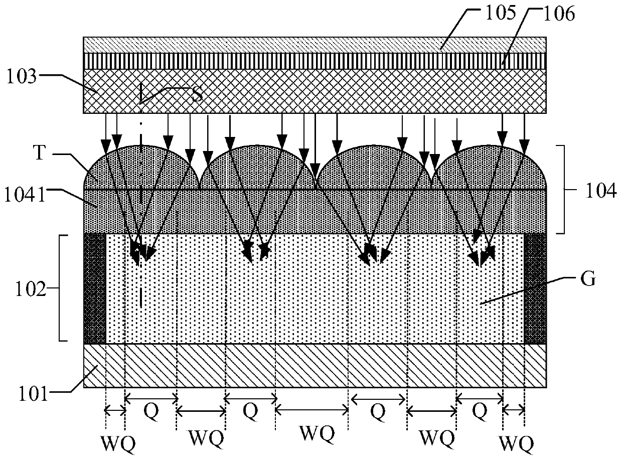
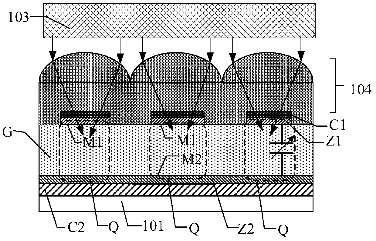
The embodiment of the invention provides a radiographic image detector. The radiographic image detector includes: a substrate; an optical image detector located on the substrate, wherein the optical image detector comprises a plurality of arrays of periodically arranged photosensitive pixels; wherein the photosensitive pixel comprises a photoelectric conversion layer, and the photoelectric conversion layer is used for converting visible light into charges; wherein the photoelectric conversion layer comprises an effective region and an ineffective region, the area sum of the effective region issmaller than 70% of the area of the photoelectric conversion layer, and the ineffective region comprises regions except the effective region on the photoelectric conversion layer. The detector also comprises a radiation conversion layer which is located at one side of the optical image detector away from the substrate and converts the radiation into visible light. A photosensitive pixel further comprises a light guide structure layer which is located between the radioactive ray conversion layer and the photoelectric conversion layer and converges visible light to an effective area. Accordingto the invention, the dark current can be effectively reduced on the premise of ensuring the photoelectric conversion output.

Description

technical field [0001] The invention relates to the technical field of detectors, in particular to a radiation image detector. Background technique [0002] Flat-panel X-ray image detectors have been widely used in digital medical diagnosis and real-time monitoring of radiation therapy. Compared with traditional X-ray film, this flat-panel image detector has the advantages of fast, low cost, low exposure, high image quality, etc., and is convenient for data storage, transmission and calculation, and can be integrated into digital medical systems. [0003] figure 1 It is a schematic diagram of a radiation image detector of related technology, such as figure 1 It includes a radiation conversion layer 103' and a visible light image detector 102', wherein the visible light image detector 102' includes a plurality of photoelectric conversion devices (only one is shown in the figure), the photoelectric conversion device includes a photodiode, and the photodiode includes p-type ...

Claims


Application Information

Patent Timeline
Patent Type & Authority Applications(China)
IPC IPC(8): H01L27/146
CPCH01L27/14625H01L27/14627H01L27/14607G01T1/2002G01T1/2018G01T1/20181G01T1/20185
Inventor 顾铁黄忠守
Owner SHANGHAI IRAY TECH
Why Eureka
Try Eureka