A Capacitance-Voltage Classification Balance Control Method for Solid-State Transformers
A solid-state transformer, capacitor voltage technology, applied in control/regulation systems, instruments, electrical components, etc., can solve the problems of large communication requirements and high complexity of solid-state transformer control, and achieve the effect of improving communication capabilities, facilitating promotion, and easy implementation.
- Summary
- Abstract
- Description
- Claims
- Application Information
AI Technical Summary
Problems solved by technology
Method used
Image
Examples
Embodiment 1
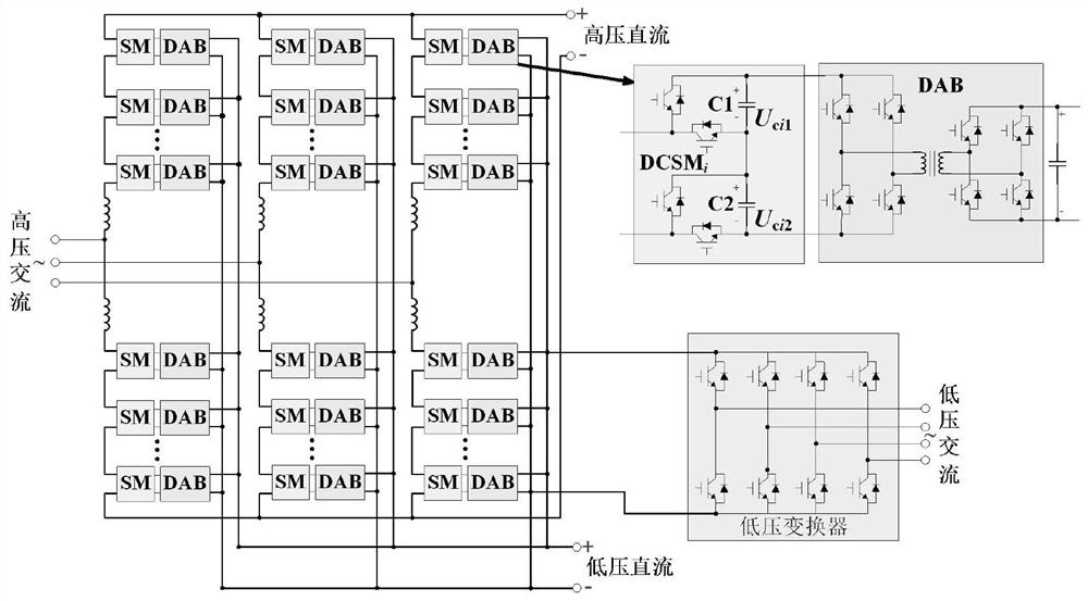
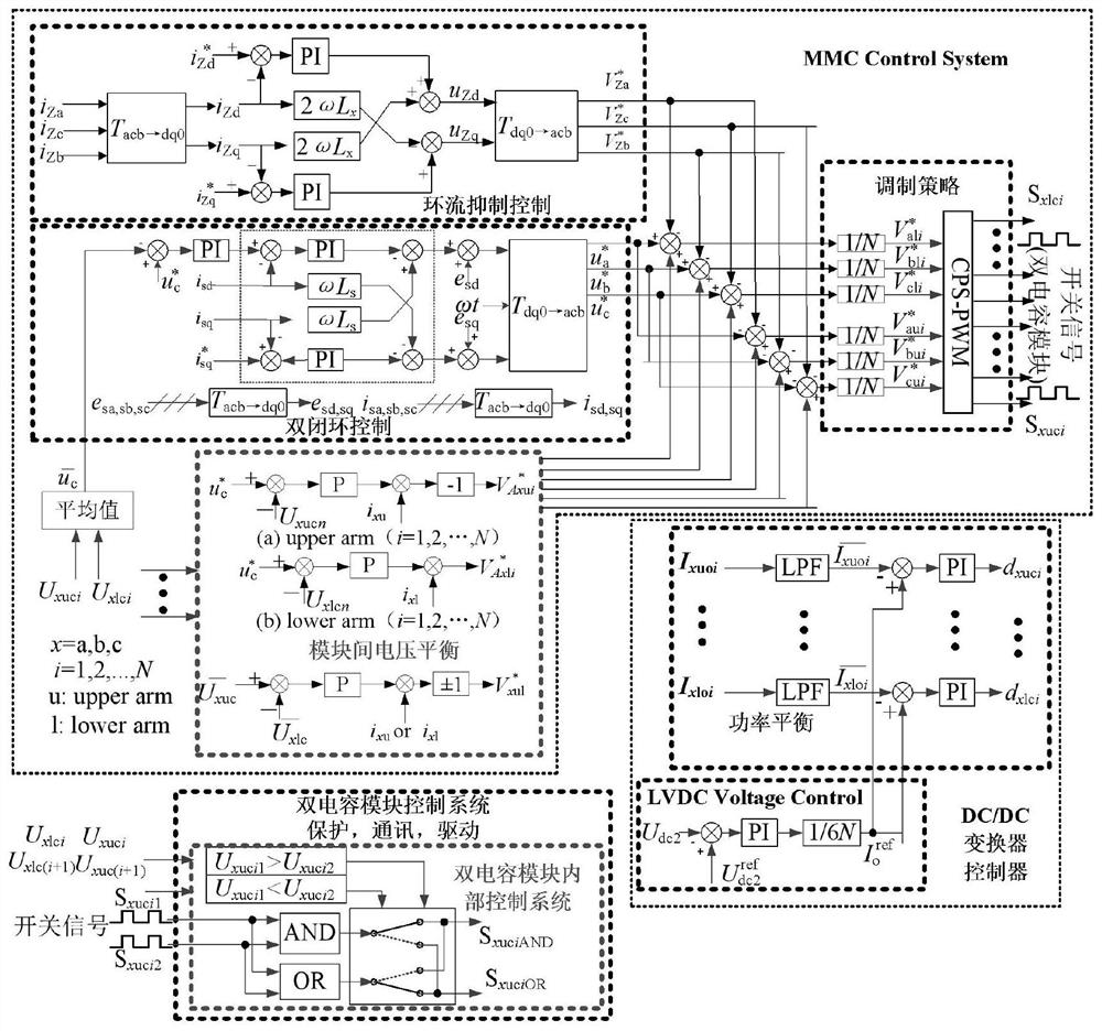
[0023] figure 2It is a typical solid-state transformer circuit diagram. The solid-state transformer is a four-port solid-state transformer composed of a modular multi-level converter and an output parallel DC / DC converter. The DC side of each dual-capacitor module is connected to a dual-active H-bridge. Converters (DABs), one end of these DABs are connected in parallel to form a DC / DC converter with outputs connected in parallel. Among them, the AC and DC ports of the modular multilevel converter can be respectively connected to the high-voltage AC bus and the high-voltage DC bus. Connect the low-voltage DC bus. image 3 Shown is the overall control block diagram of the solid-state transformer realized in the modular multilevel converter with voltage balance between modules.
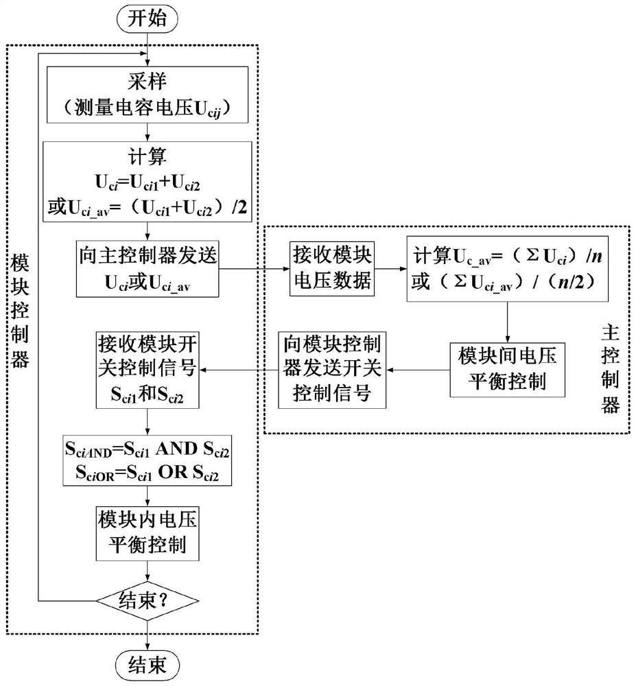
[0024] Under this topological structure and control strategy, the hierarchical capacitance voltage balancing method of the present invention is as follows: figure 1 As shown, it specifically includes...
Embodiment 2
[0034] Such as figure 2 Shown is the best embodiment of the multi-level voltage balance control method of the present invention in a typical solid-state transformer circuit. This figure is a four-port solid-state transformer composed of a modular multi-level converter and a DC / DC converter with outputs connected in parallel. . Among them, the AC and DC ports of the modular multilevel converter can be connected to the high-voltage AC bus and the high-voltage DC bus respectively. busbar. Figure 4 Shown is the overall control block diagram of the solid-state transformer in which the voltage balance between modules is realized in the output parallel DC / DC converter.
[0035] Under this topological structure and control strategy, the hierarchical capacitance voltage balancing method of the present invention is as follows: image 3 shown, including the following steps:
[0036] During the operation of the system, according to the designed sampling frequency, the controllers of...
Embodiment 3
[0045] Such as Figure 5 Shown is the best embodiment of the multi-level voltage balance control method of the present invention in other typical solid-state transformer circuits. transformer. Among them, the AC of the modular multilevel converter can be connected to the high-voltage AC bus, the module used is a dual-capacitor module, and the output DC port of the DC / DC converter with input in series and output in parallel can be connected to the low-voltage DC bus. The control block diagram and image 3 same.
[0046] Under this topological structure and control strategy, the hierarchical capacitance voltage balancing method of the present invention is as follows: figure 1 shown, including the following steps:
[0047] During the operation of the system, according to the designed sampling frequency, the controllers of each module measure and collect the capacitor voltage value U inside each module respectively. cij , where i represents the serial number of the module, an...
PUM
 Abstract
Description
Claims
Application Information
 - R&D
- Intellectual Property
- Life Sciences
- Materials
- Tech Scout
- Unparalleled Data Quality
- Higher Quality Content
- 60% Fewer Hallucinations
Browse by: Latest US Patents, China's latest patents, Technical Efficacy Thesaurus, Application Domain, Technology Topic, Popular Technical Reports.
© 2025 PatSnap. All rights reserved.Legal|Privacy policy|Modern Slavery Act Transparency Statement|Sitemap|About US| Contact US: help@patsnap.com


