Ultraviolet lamp disinfection control system

An ultraviolet lamp and control system technology, applied in heating and ventilation control systems, disinfection, heating and ventilation safety systems, etc., can solve the problems of inconvenient supervision, labor-intensive error probability, misrepresentation, etc., to improve work efficiency and save manpower , to avoid the effect of omission

Inactive Publication Date: 2020-06-09
广州市笑颜电子科技有限公司
View PDF4 Cites 6 Cited by
  • Summary
  • Abstract
  • Description
  • Claims
  • Application Information

AI Technical Summary

Problems solved by technology

However, if someone enters the area being disinfected by mistake, no one will remind him that he will be harmed by ultraviolet radiation, or if there is a power outage or the lights are turned off unexpectedly in an unmanned environment, he will not be able to be found, resulting in the fact that the disinfection is not actually completed and brings Hidden dangers, especially in kindergartens, nurseries, hospitals and other units during the outbreak of infectious diseases
[0003] Now, people have higher and higher requirements for disinfection in their environment, especially kindergartens, restaurants, etc. Relevant departments require that kindergartens, restaurants and other places need to be sterilized regularly, and there are relevant regulations that require the use of ultraviolet disinfection units (kindergartens, restaurants, etc.) restaurants, etc.) needs to be recorded, but due to the current control method of turning on the ultraviolet disinfection lamp, it can only be recorded manually. This method will have the possibility of omission, misrecording, and falsification, which will bring inconvenience to supervision At the same time, the current supervision can only conduct regular spot checks, and it is impossible to find out that the disinfection has not been implemented in the first place
[0004] Moreover, the intensity of ultraviolet light emitted by the ultraviolet disinfection lamp will decay with the time of use, and it needs to be replaced when a certain cumulative time is reached. Existing products can only record the cumulative time of use manually, which is labor-intensive and has a greater chance of error
[0005] In addition, the use of existing ultraviolet disinfection lamps is carried out in a closed environment. When someone enters the sterilized environment again, air circulation needs to be carried out immediately, which cannot meet people's demand for fresh air.

Method used


Image

  • Ultraviolet lamp disinfection control system
  • Ultraviolet lamp disinfection control system

Examples


Embodiment 1

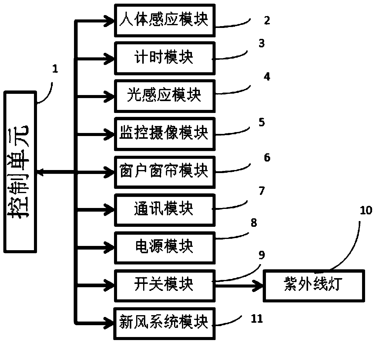
[0028] See figure 1 The ultraviolet sterilizing device shown in one embodiment of the present invention includes an ultraviolet lamp 10, a control unit 1, a human body sensing module 2, a timing sensing module 3, a light sensing module 4, a camera monitoring module 5, a communication module 7, a power supply module 8 and a switch Module 9; the control unit 1 is connected to the human body sensing module 2, the timing sensing module 3, the light sensing module 4, the camera monitoring module 5, the communication module 7 and the switch module 9; the power supply module 8 supplies power to the control unit 1. The communication module 7 includes one or more of a SIM card module, an NB-IoT network module, a GPRS network module, a WIFI module, and network wireless transmission modules such as 4G and 5G. The light sensing module 4 is used to detect the brightness of light in the disinfection area. The control unit 1 is a single chip microcomputer, and the switch control of the ultr...

Embodiment 2

[0045] refer to figure 1 and 2 The difference between the second embodiment and the first embodiment is that on the basis of the first embodiment, the ultraviolet sterilizing device also includes a window curtain module 6 for controlling the exchange of indoor and outdoor air, and the control unit 1 is connected to the signal. The intelligent terminal presets the opening and closing condition value of the window curtain; if the ultraviolet lamp is turned on, the window curtain is automatically closed; when the ultraviolet lamp completes the disinfection work, the window curtain is automatically opened according to the preset value of the intelligent terminal. The window curtain is a smart home series that can be automatically and remotely controlled to realize the automatic convection update of the indoor air and the outdoor after disinfection.

Embodiment 3

[0047] refer to figure 1 and 2 The difference between Embodiment 3 and Embodiment 1 is that: on the basis of Embodiment 1, the ultraviolet disinfection device also includes a fresh air system module 11 controlled by a fresh air system for controlling indoor air circulation, and the control unit 1 is connected to the signal. The smart terminal presets the opening and closing conditions of the fresh air system. If the ultraviolet lamp is turned on, the fresh air system is automatically turned off; when the ultraviolet lamp completes the disinfection work, the fresh air system is preset according to the smart terminal. The value is automatically turned on. The fresh air system is an air conditioner, which is pre-set on the smart terminal. When the ultraviolet light is turned on, the working air conditioner is automatically turned off, and when the ultraviolet light is finished, the air conditioner is automatically turned on for automatic indoor air circulation.


PUM


Abstract

The invention relates to the technical field of disinfection, and in particular to an ultraviolet lamp disinfection control system. The ultraviolet lamp disinfection control system comprises a plurality of ultraviolet disinfection devices, a gateway and an intelligent terminal, wherein the ultraviolet disinfection devices, the gateway and the intelligent terminal interact with each other; the ultraviolet disinfection devices comprise ultraviolet lamps; and the intelligent terminal remotely monitors and controls the ultraviolet disinfection devices through the gateway. Remote control of the ultraviolet disinfection devices is realized, and manual recording of disinfection information by workers is not needed, so that labor is saved, working efficiency is improved, and possibility of missing, misrecording and falsification is avoided. In addition, linkage with a monitoring camera shooting system, a fresh air system and window curtains is realized, and real-time monitoring and remote automatic control on the ultraviolet lamps are realized.

Description

technical field [0001] The invention relates to the technical field of disinfection, in particular to an ultraviolet lamp disinfection control system. Background technique [0002] Ultraviolet lamp irradiation is one of the most commonly used air disinfection methods at present. Because the strong ultraviolet rays produced by the ultraviolet disinfection lamp have certain damage to the skin and eyes of the human body, the operator usually chooses to avoid the time when there are many people for disinfection. Disinfect the environment in the absence of people. However, if someone enters the area being disinfected by mistake, no one will remind him that he will be harmed by ultraviolet radiation, or if there is a power outage or the lights are turned off unexpectedly in an unmanned environment, he will not be able to be found, resulting in the fact that the disinfection is not actually completed and brings Hidden dangers, especially in kindergartens, nurseries, hospitals and...

Claims


Application Information

Patent Timeline
Patent Type & Authority Applications(China)
IPC IPC(8): A61L9/20F24F11/64
CPCA61L9/20A61L2209/11A61L2209/111F24F11/0001F24F11/64
Inventor 徐明江
Owner 广州市笑颜电子科技有限公司
Why Eureka
Try Eureka