Flush joint waterproof structure for roof deformation joint

A waterproof structure and deformation joint technology, applied in the direction of roof, roof covering, building components, etc., can solve the problems of weakened waterproof performance of building structure, reduce the fluency of roof drainage, and can not meet the requirements, so as to improve impact resistance and waterproof insulation. Heat resistance, prevent cracking, increase service life effect

Inactive Publication Date: 2020-06-09
上海豪昆建筑设计有限公司
View PDF7 Cites 1 Cited by
  • Summary
  • Abstract
  • Description
  • Claims
  • Application Information

AI Technical Summary

Problems solved by technology

[0004] The above existing technical solutions have the following defects: because the waterproof wall is higher than the roof by one end, the joint design of the roof deformation joints in the existing architectural design is based on the national standard atlas. There are many options, but all Among the design choices of these joints, the concrete retaining walls are turned up on both sides of the expansion joints, and then waterproof treatment is performed. The roof after treatment will protrude from the roof height of about 40 cm. The short wall of the deformation joint is added with various covers , the use of this deformation joint treatment method on the general building roof will reduce the smoothness of roof drainage to a certain extent, resulting in weakened waterproof performance of the building structure
There are defects in some special roof treatments. For example, the roof football field cannot allow protrusions on both sides of the deformation joint due to the requirements of the overall flatness of the stadium and the overall drainage requirements of the stadium. Therefore, the methods in the national standard atlas cannot Meet the needs of this type of roof treatment

Method used


Image

  • Flush joint waterproof structure for roof deformation joint
  • Flush joint waterproof structure for roof deformation joint

Examples


Embodiment Construction

[0034] The present invention will be described in further detail below in conjunction with the accompanying drawings.

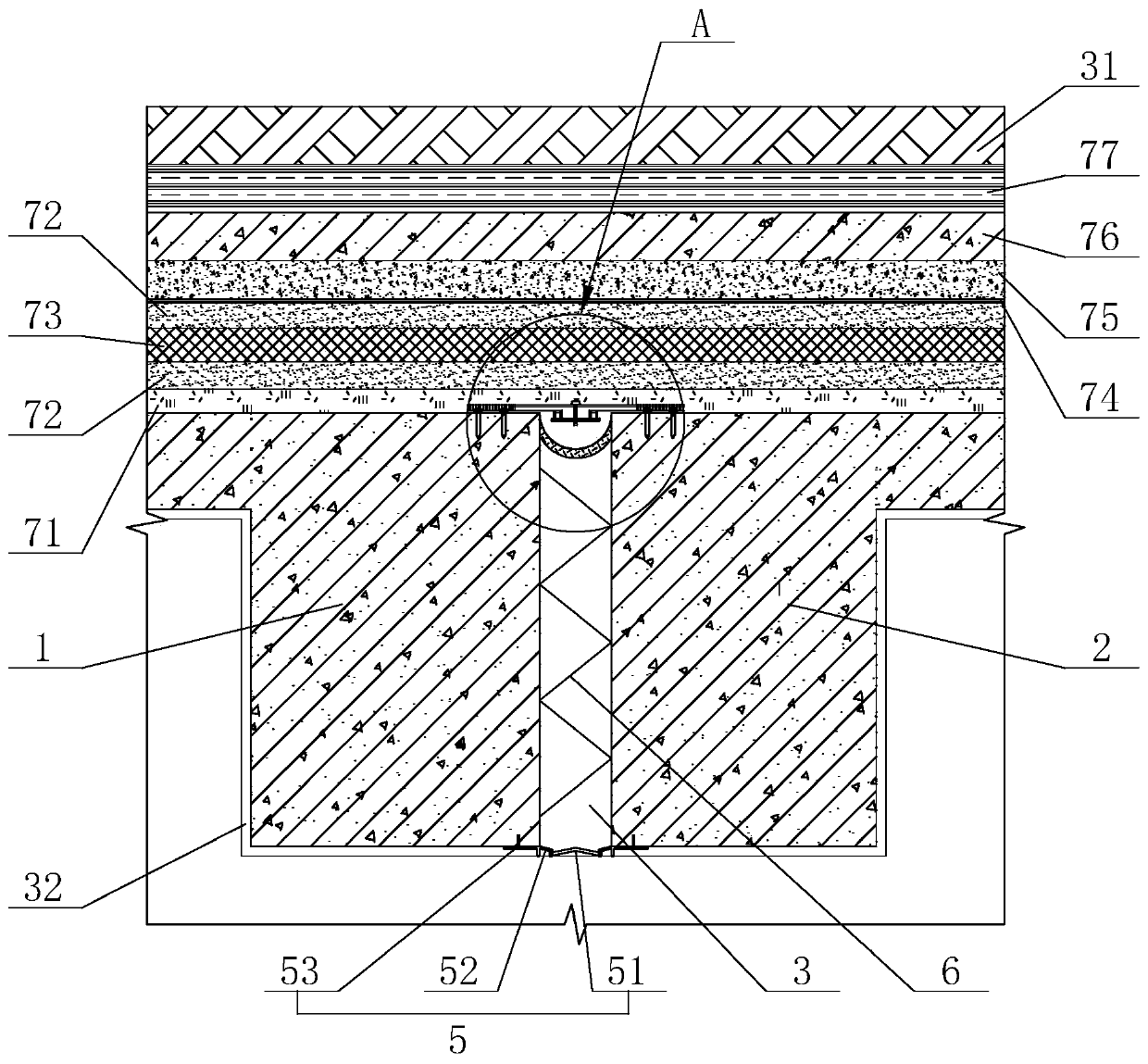
[0035] refer to figure 1 , is a flat seam waterproof structure for roof deformation joints disclosed by the present invention, comprising a first wall 1 and a second wall 2 arranged on one side of the first wall 1, the first wall 1 and the second wall 2 is made of reinforced concrete. The first wall 1 and the second wall 2 are disconnected to form vertical deformation joints 3 with a certain distance. The deformation joints 3 are provided with waterproof components and reinforcement components. The waterproof part 4 and the lower waterproof part 5.

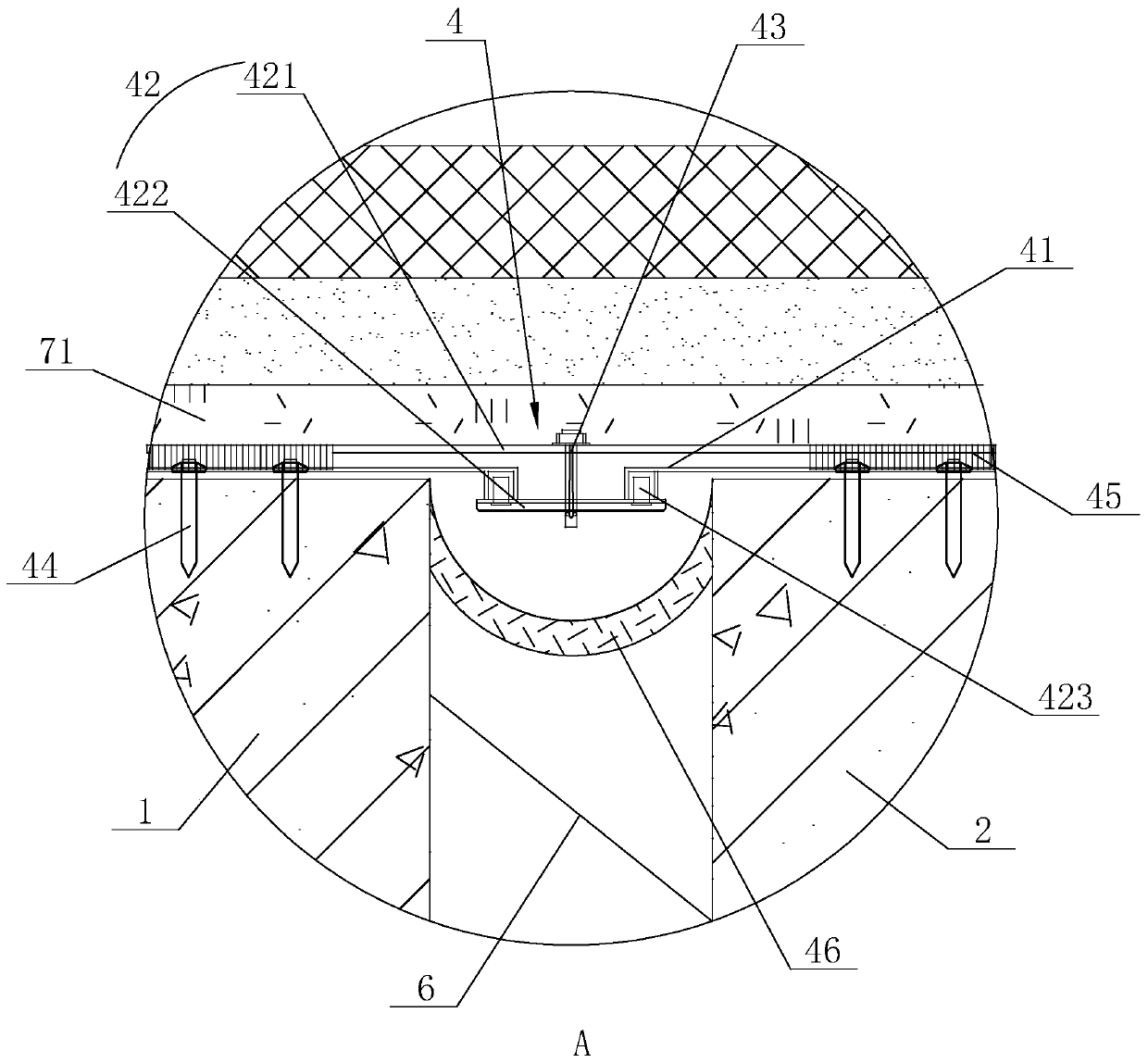
[0036] Further, refer to figure 2 , The upper waterproof part 4 includes an upper metal frame 41, a central plate 42, a central axis control rod 43 and a plurality of expansion bolts 44, in this embodiment. The upper metal frame 41 and the central plate 42 are preferably made of aluminum alloy, and the expan...


PUM


Abstract

The invention relates to a flush joint waterproof structure for a roof deformation joint. The flush joint waterproof structure comprises a first wall body and a second wall body arranged on one side of the first wall body, wherein the first wall body and the second wall body are separated to form the vertical deformation joint with a certain distance; a waterproof assembly and a reinforcement assembly are arranged in the deformation joint, and the waterproof assembly comprises an upper waterproof part and a lower waterproof part arranged at the upper end and the lower end of the deformation joint; a water stop belt is arranged below a middle shaft control rod, the two ends of the water stop belt are in lap joint with the first wall body and the second wall body, and the position, where thejoint is located, of the middle part of the water stop belt is bent downwards to form an elastic bending part with a drainage function; and a plastic surface layer is arranged on the outermost side above the first wall body and the second wall body, a reinforced concrete plate is arranged below the first wall body and the second wall body, the reinforcement assembly comprises a plurality of reinforcement plates sequentially connected in the deformation joint, and the two ends of the reinforcement plates are fixedly connected with the first wall body and the second wall body. The flush joint waterproof structure for the roof deformation joint not only ensures the continuity of the roof surface layer, but also meets the waterproof requirement.

Description

technical field [0001] The invention relates to the technical field of architectural design, in particular to a flat seam waterproof structure for roof deformation seams. Background technique [0002] In industrial and civil buildings, due to the influence of factors such as temperature changes, uneven foundation settlement, and earthquakes, additional stress and deformation will occur inside the building structure. If it is not handled properly, it will cause damage to the building, cracks or even collapse. Affect use and safety. The solutions include: strengthening the integrity of the building so that it has sufficient strength and rigidity to overcome these destructive stresses without causing damage. Firstly, the structure is disconnected at these deformation-sensitive parts in advance, and a certain gap is left to ensure that each part of the building has sufficient deformation width in these gaps without causing damage to the building. This reserved gap that divides...

Claims


Application Information

Patent Timeline
Patent Type & Authority Applications(China)
IPC IPC(8): E04B1/68E04D11/02E04D13/16
CPCE04B1/6803E04B1/6806E04D11/02E04D13/1606
Inventor 李昆仑马纳乔豪闫伟
Owner 上海豪昆建筑设计有限公司
Why Eureka
Try Eureka