Railway track energy acquisition device

An energy harvesting, railway track technology, applied in the field of rail transit, can solve problems such as power supply difficulties

Active Publication Date: 2020-06-09
SOUTHWEST JIAOTONG UNIV
View PDF5 Cites 2 Cited by
  • Summary
  • Abstract
  • Description
  • Claims
  • Application Information

AI Technical Summary

Problems solved by technology

The railway self-power supply system provides power to its supporting monitoring equipment and trackside equipment, which can solve the problem of power supply difficulties i

Method used


Image

  • Railway track energy acquisition device
  • Railway track energy acquisition device
  • Railway track energy acquisition device

Examples


Embodiment 1

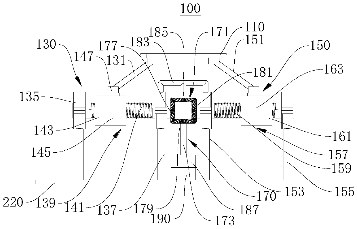
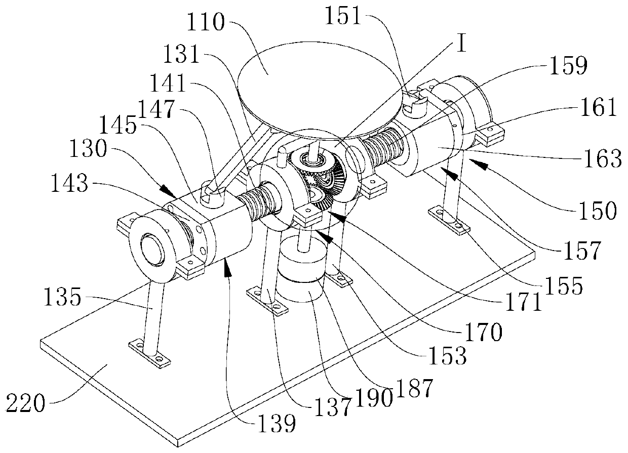
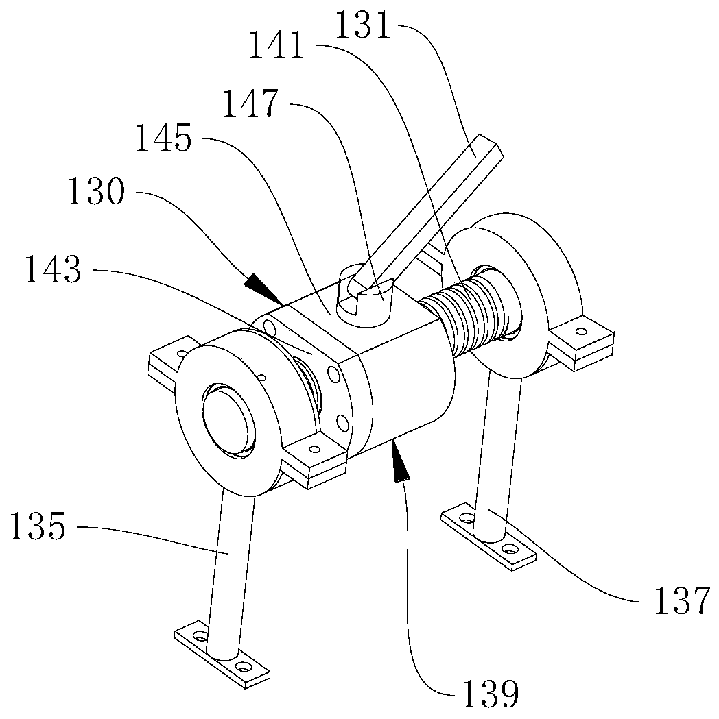
[0037] Please refer to figure 1 and figure 2 , figure 1 Shown is a schematic structural diagram of a railway track energy harvesting device, figure 2Shown is a schematic diagram of a three-dimensional structure of a railway track energy harvesting device. A railway track energy collection device 100 includes a force plate 110, a first transmission assembly 130, a second transmission assembly 150, a rotation assembly 170, a power generation assembly 190 and an energy storage assembly (not shown in the figure). The rotating assembly 170 includes a bevel gear set 171 and a main shaft 173 . One end of the bevel gear set 171 and the main shaft 173 can be connected by a card slot. The first transmission assembly 130 and the second transmission assembly 150 are connected through a bevel gear set 171, and the bevel gear set 171 is provided with a one-way bearing 175, and the one-way bearing 175 cooperates with the first transmission assembly 130 and the second transmission assem...


PUM


Abstract

The invention belongs to the technical field of rail transit, and particularly relates to a railway track energy acquisition device. The track vibration energy acquisition device comprises a stressedplate, transmission assemblies, a rotating assembly, a power generation assembly and an energy storage assembly, wherein the transmission assemblies comprise the first transmission assembly and the second transmission assembly; the rotating assembly comprises a conical gear set and a main shaft; the conical gear set is connected with one end of the main shaft; the first transmission assembly and the second transmission assembly are respectively connected with the main shaft through the conical gear set; the conical gear set is provided with one-way bearings which are matched with the first transmission assembly and the second transmission assembly to realize the continuous one-way rotation of the main shaft; the first transmission assembly and the second transmission assembly are both connected with the stressed plate; the rotating assembly is connected with the power generation assembly; and the power generation assembly is connected with the energy storage assembly. According to therailway track energy acquisition device, a railway self-powered system is used for supplying power for trackside equipment, and the problem that low-voltage power supply for the auxiliary equipment isdifficult in railway operation in remote areas is solved to a certain extent.

Description

technical field [0001] The invention belongs to the technical field of rail transit, and in particular relates to a rail energy collection device. Background technique [0002] Rail transit is a type of vehicle or transportation system in which operating vehicles need to run on specific tracks. The most typical rail transit is a railway system composed of traditional trains and standard railways. In recent years, the state has comprehensively launched railway planning and construction. After the construction of railways in alpine regions and remote areas, there will be difficulties in power supply during operation, making it difficult to use low-voltage power supplies for various electronic systems and monitoring and detection systems used to maintain railway tracks. Contents of the invention [0003] Aiming at the problem that the inspection and management of the electronic system used in the railway track in the alpine region is very inconvenient, the present invention...

Claims


Application Information

Patent Timeline
IPC IPC(8): F03G7/08
CPCF03G7/08
Inventor 吴小平张庭生朱强樊亚伦余玺张祖涛
Owner SOUTHWEST JIAOTONG UNIV
Why Eureka
Try Eureka